23
E N G L I S H
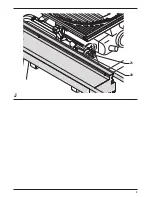
• Use the bolt (31) and nut for height adjustment
(fig. F1).
• Use the upper bolt (32) and nut to lock the
mounting rail.
• Use the set screws (33) and (34) to set the table
parallel to the blade of your sawing machine.
• Use the protruding bolt (35) and nut to set the
sliding table level with the mitre saw table (fig. F2).
Angle adjustment (fig. G)
• Set the parallel fence to a known angle and lock
the wingnut (36).
• If the angle adjustment is incorrect, loosen the
Allen screws (37) in the side of the angle beam
(38), adjusting it with the aid of a 45° triangle or
the 90° guide piece (24). Fasten the Allen screws
(37).
Instructions for use
Always observe the safety instructions
and applicable regulations.
Prior to operation:
• Check that the sawing machine is correctly
installed in saw bench mode.
• Check that all guards and fences are in perfect
working order and mounted correctly.
• Check again that both tables are perfectly parallel.
• Connect a dust extractor.
Switching on and off
Refer to the instruction manual of your
power tool.
Vertical straight cross cut (fig. E & H)
• Set the parallel fence (4) up to 1 cm before the
blade. Engage the 90° guide piece (24) in the
groove of the sliding table (2) and lock the
wingnut (25).
• Press the spring loaded fence setting guide (6) to
set its distance on the fence to the tip of the
blade and lock the star knob (27).
• Adjust the tape to show 5 cm at the edge of the
fence setting guide (6) and lock the tape (26) with
the star knob (30). The tape measure (26) is now
calibrated relative to the position of the saw blade.
• Place your workpiece against the fence.
• Set the fence setting guide (6) using the tape
measure (26) to cut the workpiece to the desired
length.
• If required, rest the end of the workpiece on the
material support (28).
• Push the sliding table (2) to the rear, feeding the
material into the blade. Do not force.
Mitre cuts (fig. I)
• Disengage the 90° guide piece from the groove
of the sliding table.
• Set the required angle using the mitre quadrant (3)
and scale (5).
• Make sure the parallel fence (4) will not be caught
by the blade.
• Proceed as for a vertical straight cross-cut.
If the sliding table is not being used (fig. C1, F1 & J)
• Loosen the star grip (21), rotate the securing
hook (20) up and hinge the sliding table down
and out of the way (fig. J). The table now rests on
the rubber stops (39) (fig. F1).
• Loosen the bolt (14) and rotate the bracket (13)
down and out of the way (fig C1).
Maintenance
Your attachment has been designed to operate over
a long period of time with a minimum of
maintenance. Continuous satisfactory operation
depends upon proper tool care and regular cleaning.
Lubrication
Your attachment requires no additional lubrication.
Cleaning
Regularly clean the attachment with a soft cloth.
Unwanted products and the
environment
Take your attachment to an authorized D
E
WALT
repair agent where it will be disposed of in an
environmentally safe way.
Summary of Contents for D271055
Page 1: ...1 D271055 ...
Page 3: ...3 A 1 6 2 3 5 4 ...
Page 4: ...4 B C2 C3 9 7 10 8 C1 11 14 13 12 1 16 15 17 18 22 7 ...
Page 5: ...5 20 21 13 13 19 1 C4 C5 ...
Page 6: ...6 24 28 30 30 26 25 27 6 4 29 24 2 3 23 D E ...
Page 7: ...7 38 37 36 35 F1 G F2 32 39 31 33 34 ...
Page 8: ...8 4 3 5 30 27 6 25 2 4 28 26 H I ...
Page 9: ...9 20 21 J ...

