


E NGLISH
7
before adjusting or changing set-ups or
when making repairs. Be sure the trigger
switch is in the OFF position. An
accidental start-up can cause injury.
Side Handle (fig. 1)
WARNING:
To reduce the risk of
personal injury,
ALWAYS
operate the
tool with the side handle properly
installed and securely tightened. Failure
to do so may result in the side handle
slipping during tool operation and
subsequent loss of control. Hold tool
with both hands to maximize control.
A side handle comes assembled with this rotary
hammer. The side handle (c) can be fitted to suit
both right-hand and left-hand users.
TO ADJUST THE SIDE HANDLE
Loosen the side handle (c) by turning it
counterclockwise.
Rotate the side handle to the desired position.
Tighten the side handle by turning it clockwise.
TO CHANGE SIDES
For right-hand users:
slide the side handle
clamp over the chuck, handle at the left.
For left-hand users:
slide the side handle
clamp over the chuck, handle at the right.
Reversing Lever (fig. 1)
The reversing lever (h) is used to reverse the rotary
hammer for backing out fasteners or jammed bits
in the drill-only function.
CAUTION:
When reversing to clear
jammed bits, be ready for strong
reactive torque.
To reverse the rotary hammer, turn it off and align
the reversing lever (h) with the yellow arrow
pointing backward (viewed when holding drill in
operating position).
To position the lever for forward operation, turn the
rotary hammer off and align the reversing lever (h)
with the yellow arrow pointing forward (viewed
when holding drill in operating position).
Mode Selector (fig. 2)
CAUTION:
Tool must come to a complete
stop before activating the mode selector
button or damage to the tool may result.
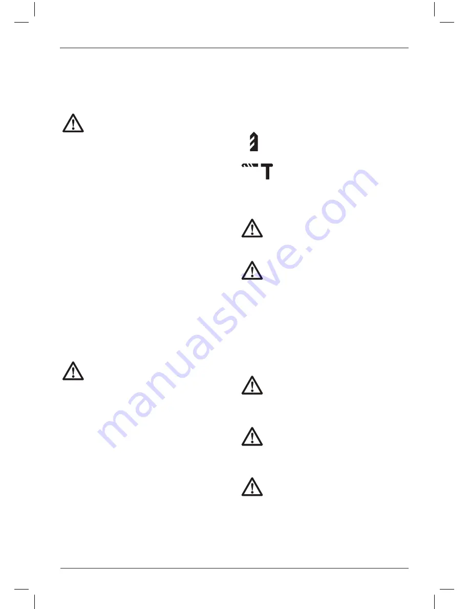
To select the operating mode, press mode
selector button (f) and turn the mode selector
(g) so the yellow arrow points to the
corresponding symbol.
1.
2.
3.
1.
Release the mode selector button and check
that the mode selector switch is locked in
place.
NOTE:
The yellow arrow on the mode selector
MUST
be aligned with one of the symbols at all
times. There are no operable positions between
the positions.
ROTARY DRILLING MODE
Userotary drilling mode for wood,
metal, and plastics.
HAMMERDRILL MODE
Use this mode for masonry drilling.
2.
Inserting and Removing SDS Plus
®
Accessories (fig. 4)
WARNING:
Always wear gloves when
you change accessories. The exposed
metal parts on the tool and accessory
may become extremly hot during
operation.
WARNING:
Do not attempt to tighten or
loosen drill bits (or any other accessory)
by gripping the front part of the chuck and
turning the tool on. Damage to the chuck
and personal injury may occur.
This tool uses SDS Plus
®
accessories We recom-
mend to use professional accessories only.
To insert bit, push and rotate bit until it locks in
place. The bit will be securely held.
To release bit, pull the chuck sleeve (e) back and
remove the bit.
SDS Plus
®
Chuck (fig. 4)
WARNING:
To reduce the risk of
serious personal injury, turn tool off
and disconnect tool from power
source before making any adjust-
ments or removing/installing
attachments or accessories.
WARNING:
Burn Hazard.
ALWAYS
wear
gloves when changing bits. Accessible
metal parts on the tool and bits may get
extremely hot during operation. Small bits
of broken material may damage bare
hands.
WARNING:
Do not attempt to tighten or
loosen drill bits (or any other accessory)
by gripping the front part of the chuck and
turning the tool on. Damage to the chuck
and personal injury may occur.
To insert bit, insert shank of bit about 19 mm
(3/4")into chuck. Push and rotate bit until it locks in
place. The bit will be securely held.
Summary of Contents for D25011K
Page 1: ...D25011K ...
Page 2: ...3 English Copyright DEWALT ...
Page 3: ...a c b Figure 1 Figure 2 1 d a b e f ...
Page 4: ...2 Figure 3 Figure 4 ...


