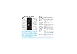
devolo BPL Modem MV
7
4 Description of the connections
A
Supply voltage connection
– Connect the terminals to the corresponding DC current power
supply conductors here.
BA
Part modem A BNC connection
– Connect the BNC connections to the corresponding BNC
feed line to the medium-voltage signal couplers.
BB
Part modem B BNC connection
: Connect the BNC connections to the corresponding BNC
feed line to the medium-voltage signal couplers.
DA
RJ45 Ethernet jack of part modem A
– RJ45 Ethernet jack part modem A for the connec-
tion of compatible Ethernet devices over an RJ45 Ethernet cable.
DB
RJ45 Ethernet jack of part modem B
– RJ45 Ethernet jack part modem B for the connec-
tion of a compatible Ethernet device over an RJ45 Ethernet cable.
CA
Back-To-Back connection of modem A
– connect the BPL Modem MV to
CB
using the
included RJ45 patch cable.
CB
Back-To-Back connection of part modem B
– connect the BPL Modem MV to
CA
using
the included RJ45 patch cable.
EA
Part modem A control display
– is illuminated steady GREEN as soon as part modem A
has a PLC data connection.
EB
Part modem B control display
– is illuminated steady GREEN as soon as part modem B has
a PLC data connection.
Fig. 1: Description of the connections
Summary of Contents for BPL Modem MV
Page 1: ...devolo BPL Modem MV ...
Page 2: ...BPL Modem MV ...


