


SB-2-601-C Page 3
Drip Free Mode "D/F" -
To operate in the drip free mode, rotate the
valve with a screwdriver or coin so that the hole in the valve slot is
aligned with the "D/F" on the lid. See Figure 3.
Do not probe through the valve slot hole while the valve
is in D/F position. These holes are sealed by lid gasket and
damage could result. See Figs. 2 & 3.
Valve Movement
Do not forcibly rotate the valve. If it will not move freely, soak in
solvent or remove the lid assembly from the cup and press down on
the top of the valve until it breaks free. The valve has free travel
vertically of about 1/8". This can be used to push out the lid gasket.
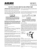
Figure 3 - Drip Free Mode
INSTALLATION
1 .
Position yoke at right angle to gun body with vent hole in lid
toward rear and lever of cam (26) toward front of gun.
2.
Fasten cup lid assembly to gun by attaching nut (25), see
Figure 5, to fluid inlet nipple on gun. Tighten nut with wrench
only until snug.
3 .
Strain material to be sprayed through a 60-90 mesh screen
before pouring into cup.
4.
Engage pins on cup into yoke and tighten yoke by moving
lever of cam clockwise.
MAINTENANCE
Lid Repair/Replacement:
1 .
To replace a damaged part, use a 5/16" Allen wrench to loosen
and remove adapter (24), nut (25)and yoke and cam (26). Lid
and tube assembly are now loose for replacement.
2.
Replace damaged parts on the lid and tube assembly. The cam
lever should be located on opposite side of lid from valve (27).
Gasket shown
partially removed
Valve in
Drip Free
Position
Channel
Vent Hole
(Do Not Probe)
Valve slot
hole sealed -
(Do Not Probe)
Lid Top
O
D/F
Lid Underside
Valve in
Open
Position
Channel
Vent Hole
(Do Not Probe)
Valve slot
hole can be
probed to
clean.
Gasket
Channel
Channel
Vent
Hole
Lid Underside
Lid Top
Gasket shown
partially removed
O
D
/F
Figure 2 - Open Vent Mode
3.
Apply sealant (Loctite #262) to the first two full threads of
adapter. Insert threaded end of adapter (24) into open end of
nut (25).
4 .
Install adapter (24) and nut (25) in top of lid and tube assembly.
Use a 5/16" Allen wrench to tighten firmly (10-12 foot pounds).
Valve and Lid Gasket Replacement:
1 .
To remove a damaged valve (27) or lid gasket (28), press down
on top of valve until it breaks free.The valve pushes the lid
gasket from the seat. The lid gasket may now be removed from
the lid. Continue pressing hard on the valve to remove it from
the lid.
2 .
Install replacement valve (27) through bottom of lid so that the
valve tab is toward center of lid. Snap in place. If necessary,
use a plastic mallet or screwdriver handle to tap the valve in
place. Press the lid gasket (28) firmly in the lid using the end of
a crescent wrench handle. Insert the side with the black marks
first.
CLEANING
General:
For routine cleaning, it is not necessary to remove the lid
gasket. It is not necessary or desirable to remove the valve for any
cleaning procedure. The valve can be depressed from the outside
to assist in removal of the gasket for gasket replacement or when
cleaning dried paint from the channel. The valve should not be
forced past the shoulder which retains it in the lid except for
replacement.
The cam and mating surfaces on the lid and yoke normally don't
require removal for cleaning. Spraying some materials containing
PTFE
®
or similar materials can necessitate more frequent cleaning
and possible disassembly of the cam. The ovespray containing
PTFE
®
can build up on the cam and mating surfaces causing a
condition where the cam may loosen during use.
Note
Clean cam and mating surface on lid with a solvent soaked
Scotch™ pad and blow dry. If cam loosening persists,
removal of the yoke and cam will be required for more
thorough cleaning of these parts. Again, use a solvent
soaked Scotch™ pad for this purpose. Reassemble lid.
Air Pressure:
Always clean with reduced air pressure. An air
pressure no greater than 15 to 20 psi will allow quick and thorough
cleaning of the cup and gun and at the same time will:
1 .
Minimize the amount of solvent atomized into the air.
2 .
Prevent possibility of damage to cup from excessive back
pressure.
3 .
Reduce the force with which solvent is expelled from the vent.
Cleaning Procedures:
1 .
Empty paint from cup and add small amount of clean solvent.
The amount required will vary with different coatings and
solvents.
2.
Shake cup to wash down inside surfaces. Then spray solvent
at low air pressure (15-20 psi) to flush out fluid passages.
3 .
Pour out solvent and add same amount of clean solvent.
4a. Again, shake cup. Loosen air cap. Hold a folded cloth over
front of gun and invert cup over solvent receptacle. Trigger
with short bursts to back flush vent channel. With valve in the
D/F
position, solvent will be expelled with force from the
channel vent hole in lid.
Alternative to Step 4a.
4b. Shut off air to gun. With valve in the
D/F
position, invert cup
over solvent receptacle. Trigger gun. Allow solvent to drip out
channel vent hole in lid for several seconds, or until clean
solvent is seen.
IMMERSION
Since all materials in the cup are highly solvent resistant, the cup
assembly may be immersed for cleaning. Immersion should not
exceed 24 hours. The use of paint strippers should be avoided
because strippers will affect the aluminum as well as other nonme-
tallic components. If the lid gasket has become swollen from
prolonged exposure to solvents, it will return to its original size
without loss of properties when allowed to dry.
The position of the valve is indicated by alignment of the hole in the
valve slot with the marks cast on the lid. These positions are
identified as on the lid as "O" for vent open and "D/F" for drip free.
OPERATION
Open Vent Mode "O" -
To operate in the open vent mode, rotate the
valve with a screwdriver or coin so that the hole in the valve slot is
aligned with the "O" on the lid. See Figure 2.
If the valve slot hole should plug while operating in the "O" vent
mode, use a pointed tool such as a nail or drill bit to probe through
the valve slot hole to clear away the obstruction.


