background image

65 Aleksandar Stamboliyski Str., 8000 Bourgas, Bulgaria

Tel: +359 56 820027, Fax: +359 56 836700

E-mail: [email protected] ,Web: www.devabroadcast.com

- 16 -

Panel Indicators, Switches and Connectors

FRONT PANEL – LEFT AND RIGHT AREAS

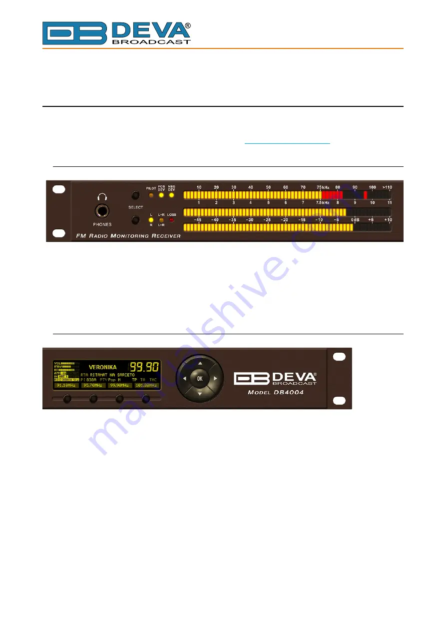
The DB4004 front panel can be provisionally divided into two main areas – Left Area and Right 

Area. A brief description of controls and switches, indicators and displays located in both areas is 

given below. For detailed information please refer to “Operation” on page 19.

Left Area

At the extreme left is located the Phones connector. Next to them are the sub areas of 

FM 

MODULATION  METERING

  and 

AUDIO  DEMOD  METERING

  with  the  appropriate 

SELECT 

buttons and LED indicators. Both areas contain 60 segments LED bargraphs. The upper one is 

used to indicate the Total Deviation, the Positive or Negative deviations divided each other and the 

Pilot signal as well. The lower bargraphs are used to show the demodulated audio according to the 

mode selected by the 

SELECT

 button on the left of them.

Right Area

OLED Display

– signals received by DB4004 can be viewed and analyzed by the built-in OLED display. This is 

the display to visualize all the measurements of the received signal and show the various DB4004 

settings.

Soft Buttons

– used to navigate through the menus, quickly access the parameters, modes and functions and 

to alter their values. Their functions vary in accordance with the selected menu. On the bottom side 

of the OLED display are located Soft Buttons indicators and they alter their meaning following 

the function currently selected by the Soft Buttons. Pressing of a Soft Button, causes a visual 

effect of pressing the appropriate button on the OLED Screen. Soft Buttons will be referred as 

SB1


(leftmost one), 

SB2

SB3

 and 

SB4

 (rightmost one) further in this manual. 

Navigational Buttons

– 

UP

 and 

DOWN

LEFT

 and 

RIGHT

 and 

OK

 buttons are used for frequency selection and 

similarly  to  the 

Soft  Buttons

  to  navigate  through  the  menus  selecting  various  functions  and 

parameters of the DB4004.

Summary of Contents for DB4004

Page 1: ...MAINTENANCE AND OPERATION INSTRUCTION MANUAL Publish Date 17 Aug 2015 DB4004 DSP based FM Radio Monitoring Receiver with TCP IP Connectivity ...

Page 2: ...tons 16 Navigational Buttons 16 Rear Panel 17 Rear Panel Alarm Terminal 18 Operation 19 A Word about Measurement Limitations 19 Signal Strength 19 Multipath Distortion 19 Co channel Interference 20 First Time POWER ON 21 Front Panel Readout Section Left Side 22 Phones 22 Bargraphs and LED Indicators Select Buttons 22 FM MODULATING METERING 22 SELECT Button 22 AUDIO DEMOD METERING 22 L R L R L R 23...

Page 3: ... Screen 60 Bandscan Screen 61 Status Screen 62 Log Screen 63 General Settings Screen 64 Tuner Settings Screen 65 Alarms Settings Screen 66 Alarm notifications 66 Alarm 66 Logger Settings Screen 67 Logger Channel Settings 68 Channel 68 Alarm Notification Type 68 Alarm 68 Communication Settings Screen 69 Network 69 HTTP Server 69 FTP Server 69 SNMP Agent 70 Syslog 70 GSM Modem 70 Application Server ...

Page 4: ...Factory Defaults 72 Reboot 72 APPENDIX 1 Alarm Triggers 73 Alarm Triggers 73 Alarm Notifications 75 APPENDIX 2 List of DB4004 settings 76 WARRANTY TERMS AND CONDITIONS 84 Product Registration Card 85 ...

Page 5: ...THIS PAGE IS INTENTIONALLY LEFT BLANK ...

Page 6: ...ved us a reliable business partner and a valuable asset as our dealers worldwide would confirm In constant pursuit of precision and long term satisfaction DEVA enhances the reputation of our partners and clients alike Furthermore we have already a proven merit as a credible partner provider Our portfolio offers complete line of high quality and competitive products for FM and Digital Radio Radio N...

Page 7: ...s enable alerting for most the important signal components and parameters to be generated and are fed to the Rear Panel Alarm Terminal for remote alarm notification The DB4004 is designed to support USB and LAN communication interfaces allowing flexibility in remote connection and control of the unit The DB4004 is the most cost effective way for regular monitoring of the quality and continuity of ...

Page 8: ...ereo Decoder Real Time Audio Program Streaming Remote Listening via optional GSM modem Built in 50 channel Data logger Built in WEB and FTP server Easy to use WEB interface Apple and Android devices support SNTP for automatic synchronization of the built in clock RDS and RBDS decoder with BER meter Alarm dispatch via E mail SMS SNMP and GPO Complete status reporting with SMS via optional GSM modem...

Page 9: ... Increments 27kHz 157kHz Auto Frequency Response 0 1 dB 10 Hz to 86 kHz MPX Power 12 dBr 20 sec integration Dynamic range 90 dB STEREO DECODER Frequency Response L and R 0 1 dB 10 Hz to 15 kHz SNR Stereo 60 dB 50 µs de emphasis THD 0 15 1kHz 0 4 10Hz 15kHz 50µs de emphasis Separation 50 dB 50 Hz to 10 kHz 50 µs de emphasis Crosstalk 52 dB RDS DECODER Standards European RDS CENELEC United States RB...

Page 10: ...S 0 5 kHz 1 to 12 kHz 0 2 kHz resolution Audio 1 dB 10 0 to 55 0 dB 0 1 dB resolution OUTPUTS Composite 3 5 Vp p 75kHz 75Ω unbalanced BNC Connector Audio L R 12 dBm 600Ω balanced XLR Connector AES3 L R 5 0 Vp p 110Ω balanced XLR Connector SPDIF L R 3 0 Vp p 110Ω unbalanced BNC Connector Optical L R Transmitter TOSLINK Alarms Programmable terminals on rear panel optoisolated Headphone 6 3mm 1 4 Pho...

Page 11: ...demodulation Stereo decoding Metering Control and Communication CPU Ethernet USB User controls L R MPX Rear Panel Analog Audio SPDIF AES EBU Optical MPX Out GPO GSM Modem Front panel LED OLED Because of the all digital minimalist discrete component nature of device circuitry we have not provided schematic diagrams of the DB4004 in this Manual Please note that NO USER SERVICEABLE COMPONENTS INSIDE ...

Page 12: ...has to be switched off and the mains cable unplugged When the equipment is open the power supply capacitors have to be discharged by the help of a suitable resistor During servicing unprotected and operating equipment never touch bare wires or circuitry use insulated tools only never touch metal semiconductor cases because they may carry high voltages For removing and installing electronic compone...

Page 13: ...ooms with high humidity dusty places or other aggressive conditions Although it is expected that a DB4004 will be installed close to exciters or transmitters of even higher power please practice reasonable care and common sense in locating the unit away from abnormally high RF fields Please use only already checked power supply cables and sources The shielded cables usage is strongly recommended W...

Page 14: ... proper outdoor FM antenna antenna location and direction The three most popular antenna types are omni directional unidirectional dipole and directional multi element array antenna The omni directional Antenna is not a good choice for using with DB4004 because of the low antenna gain the very bad signal to noise ratio compared to any directional antenna and its high multipath interferences recept...

Page 15: ...he AC Power make certain that the internal Power Switch and the fuse rating are in accordance with the mains supply at your location ATTENTION DB4004 Power Supply Factory Settings are 100 240 VAC 1 Amp Fuse CAUTION Permanent damage will result if improper AC supply voltage is applied to the DB4004 device Your warranty does not cover damages caused by applying improper supply voltage or use of an i...

Page 16: ...sed to show the demodulated audio according to the mode selected by the SELECT button on the left of them Right Area OLED Display signals received by DB4004 can be viewed and analyzed by the built in OLED display This is the display to visualize all the measurements of the received signal and show the various DB4004 settings Soft Buttons used to navigate through the menus quickly access the parame...

Page 17: ... 1 Mains connector 110 240VAC IEC 320 C14 type 2 Fuseholder 1A 3 Audio Left Output XLR 4 Audio Right Output XLR 5 Audio AES EBU Output XLR 6 Audio SPDIF Output RCA 7 Audio Optical Output TOSLINK 8 MPX Output BNC 9 RF Input 1 Antenna 1 BNC 10 RF Input 2 Antenna 2 BNC 11 Ethernet T BASE10 100 RJ45 12 USB type B 13 GSM Modem Male D Sub 15 pins High Density 14 GPO Optoisolated Female D Sub 15 pins ...

Page 18: ...dcast com 18 REAR PANEL ALARM TERMINAL 1 2 3 4 5 6 7 8 9 10 11 12 13 14 15 1 GPO1 Collector 9 GPO1 Emitter 2 GPO2 Collector 10 GPO2 Emitter 3 GPO3 Collector 11 GPO3 Emitter 4 GPO4 Collector 12 GPO4 Emitter 5 GPO5 Collector 13 GPO5 Emitter 6 GPO6 Collector 14 GPO6 Emitter 7 GPO7 Collector 15 GPO7 Emitter 8 GND LOAD 1 9 GPO1 LOAD 1 9 GPO1 ...

Page 19: ...eing received where the rule the more the better is in force To reach this indicator activate LEVELS menu Multipath Distortion In FM reception regardless of overall signal strength a very important consideration is that obstacles which an FM signal may encounter in the line of sight path tend to reflect and disperse the signal in many directions In many locations especially in urban areas where ma...

Page 20: ...ct One method to identify adjacent channel interference is to observe independent positive and negative deviation readings If the positive deviation is considerably higher then the negative one interference from a strong station above the monitored frequency would be indicated and vice versa In this example the negative deviation can probably be trusted as an indication of total carrier modulation...

Page 21: ... the settings and parameters will be held by the DB4004 s non volatile memory and used on switching on of DB4004 Plug the headphones into the front panel jack PHONES and using the LEFT or RIGHT Navigational Buttons start tuning in Find a strong local station that even with a short wire antenna could be clearly heard on the phones If needed try repositioning the antenna in order to improve receptio...

Page 22: ... change mode of the LED bargraph indicators and associated LED indicators Possible selections are POS DEV NEG DEV POS DEV NEG DEV PILOT AUDIO DEMOD METERING two 60 segments LED bargraphs showing Left and Right or L R and L R demodulated audio By default the AUDIO DEMOD METERING displays left and right channels of the stereo pair with the L R indicator lighted It is recommendable leaving this displ...

Page 23: ... indicating currently selected mode LOSS indicating that the audio of the Left and or Right stereo channel is lost DB4004 can detect program audio loss and alarm is initiated whenever any of the Left or Right channels of the stereo pair drops below selected threshold for certain time The LOSS detection threshold level and time can be adjusted from Settings Device Loss menu This function is not aff...

Page 24: ...9 56 836700 E mail office devabroadcast com Web www devabroadcast com 24 FRONT PANEL LCD DISPLAY NAVIGATIONAL SOFT BUTTONS RIGHT SIDE Display The DB4004 s OLED display has three function areas Header Soft Buttons and Main Screen Working area OLED Display with its function areas ...

Page 25: ... show the phones audio level Indicator to show currently selected IF band pass filter bandwidth Having three different de emphasis selections the question arises which one to select As well known one of the problems with the high quality VHF FM transmissions is that the increased audio bandwidth means that background noise can often be perceived It is particularly noticeable towards the treble end...

Page 26: ...e page it is linked with Most of the pages have the same or similar functionality distinctive segments areas Pressing of a specified Soft button causes a visual effect of pressing the appropriate Soft button on the OLED Display Function Menu Page Parameter to be changed etc that are linked to a specified Soft button will appear as inscription on the button Example discard changes being made applyi...

Page 27: ... contains selectable icons and software buttons for selecting modes and functionalities of this device Pressing Left and Right arrow buttons changes icon selection of the Menu Page An icon is selected when it receiver the rectangle focus frame around it Short pressing of the OK button on selected icon will make a transition to corresponding page On figure below the Bandscan icon is selected The fo...

Page 28: ...utes of the decoded RDS signal if present and big indicator of currently selected frequency Pressing any of the Soft Buttons will set to the appropriate preset Preset explained PRESET is a pre saved set of parameters for instant automatic recall later on Creating a new Preset Navigate to page of the DB4004 in which Soft Buttons are assigned to Preset In such page the labels of the soft buttons are...

Page 29: ...e shown on the display If there is no data from previous bandscan the empty grid will be displayed Since more space for data plot is needed the Header area is not shown on that page The labels of the Soft buttons are hidden automatically short time after soft button is released There is three control states in Bandscan page Span control Marker control and Parameter control The states can be identi...

Page 30: ...will be changed alternatively between Marker and Span on every SB3 press Short pressing OK button in either Marker or Span control states will make a transition to Parameter control state The page will stay in that state until OK button is pressed again or a timeout of 2 seconds is elapsed whichever occurs first Simplified state diagram of the control states transitions is shown on figure below Sp...

Page 31: ...the data plot Possible values are between 3 and 21 MHz in 1 MHz increments Note that changing X span may also change the center frequency to keep data plot in bounds On each key press next span value is selected and displayed briefly on the screen 5MHz X span is selected SB1 cycles through available span values for Y axis of the data plot Possible values are 30 60 90 and 120 dBµV Note that changin...

Page 32: ...r center frequency depends from currently selected X span Selected value for center frequency is briefly displayed on the screen 95 MHz center frequency is selected Up Down Buttons changesYaxis reference the value for the bottom of theYscale Permitted values are from 20 dBµV in 10 dBµV increments The upper limit of Y reference depends from currently selected Y span Selected Y reference is briefly ...

Page 33: ...ppear on the left side of the data plot If both markers are visible the differential Marker B Marker A values become available at the bottom left Selected marker is drawn with highlighted dashed line the marker readout is highlighted also There can be only one selected marker at the time If only one marker is visible it is always selected Marker A is shown Marker B is selected The logic of transit...

Page 34: ...scan process Setting the value of this parameter to Start will start the bandscan process During bandscan the LED bargraphs are turned to stylized box shaped progress indicator The information for bandscan progress is also shown on right bottom corner of data plot After bandscan completion the value of the Bandscan parameter is set to Stop automatically Bandscan in progress Running bandscan can be...

Page 35: ...ermined on the base of Fast Fourier Transform The data from last selected FFT source signal since DB4004 power up will be shown on the display FFT with MPX selected as signal source The control states of FFT page are identical to the controls states of Bandscan page see Span controlstate onpage31 Markercontrolstate onpage33 Parametercontrolstate onpage34 The X Span Y Span Center Frequency Y Refere...

Page 36: ...nal source is overlayed at right bottom corner of the data plot select active antenna input of DB4004 sets the Window Function to calculate the FFT The possible values of the parameter are Rectangle Barlett Blackman Hamming von Hann and Flat top More information regarding Window Function utilizing can be found on http zone ni com devzone cda tut p id 4844 indicatesbuffernumberstakenintoaccountinca...

Page 37: ... power up will be shown on the display Scope with RDS selected as signal source The display appearance and control states of Scope page are identical to the controls states of Bandscan page see Span control state on page 31 Marker control state on page 33 Parameter control state on page 34 The X Span Y Span Center Frequency Y Reference and Markers can be changed in similar way Each signal source h...

Page 38: ...een Left and Right audio channels is illustrated above This graphic is used to assess mono compatibility of the audio material as well as visualizing the stereo image or balance of the material Experienced users of this type of display can easily detect the differences between mono signals pan pot stereo and true stereo signals The audio levels for both left and right channels are given in kHz But...

Page 39: ...nds New peak value sample is added to data graph on every 125 ms 20 seconds for MPX power Up to 20 seconds of measurement history is available for each parameter The most recent moment in time is on the right side of the graph The name and the unit for Y axis of currently measured parameter is displayed on top left corner of data plot On the right side of the display a bargraph indicator is used t...

Page 40: ...el from 0 to 50 in percent Total MPX deviation from 0 to 125 in kHz MPX power from 12 to 12 in dBr Due to 20 second integration of MPX power calculation the time span for MPX power graph is in minutes Up to 48 minutes of MPX power history is available Pilot level from 0 to 15 in kHz RDS level from 0 to 15 in kHz Left Right Main level from 60 to 10 in dB Left Right Sub level from 60 to 10 in dB Lef...

Page 41: ...otes the measurement range of the parameter The name and measurement unit of the parameter is shown above corresponding bargraph Group 1 This group shows RF carrier related parameters RF level in dBµV at the selected antenna input The attenuator position is taken into account in level calculation Frequency offset of the RF carrier in kHz With this parameter the misalignment between the modulation ...

Page 42: ...parameters These two bargraphs shows the deviation from positive and negative component of MPX signal In wideband FM used in wireless broadcasting the instantaneous frequency varies above and below the frequency of the carrier with no modulation When the instantaneous input wave has positive polarity the carrier frequency shifts in one direction when the instantaneous input wave has negative polar...

Page 43: ... the MPX signal is measured This is measured in the bandwidth of approximately 80 kHz up to 150 kHz Stereo Blend bargraph higher is better In stereo signals the difference L R component of the MPX signal is more susceptible to disturbances than the sum L R signal Therefore the separation of the left and right audio channels can be reduced in order to reduce the audibility of the disturbance This r...

Page 44: ... the following input signals Signal Level Multipath Ultrasonic Noise 2 4 6 8 10 12 5000 10000 15000 20000 Response of the FM High Cut function for several reduction values Soft Mute bargraph lower is better If disturbances are present in the received signal the perceived effect can be reduced by attenuating the audio signal This reduction of audio volume is called soft mute Soft Mute depends on th...

Page 45: ...gas Bulgaria Tel 359 56 820027 Fax 359 56 836700 E mail office devabroadcast com Web www devabroadcast com 45 RDS decoder page Short press SB3 from Menu page The transition to RDS decoder page will be made RDS page main view RDS AF list view ...

Page 46: ...6700 E mail office devabroadcast com Web www devabroadcast com 46 RDS Statistics view RDS Group Sequence view RDS Raw Data view Button assignments OK Transition to Main menu page Left Right Changes current frequency Up Down Changes currently displayed RDS page view SB1 SB4 Fast Presets ...

Page 47: ... Menu page and short press OK button on it The transition to Settings page will be made The device settings are organized as hierarchical tree menu Settings menu Similar parameters are grouped in sections branches The overall view of the Settings menu is shown on the figure below Tuner section branch from the root Settings menu is selected Frequency parameter from Tuner branch is selected ...

Page 48: ...rameter editor is shown and edit mode is activated Up Down If edit mode is active changes the value of the selected parameter Otherwise will move selection in corresponding direction up down Left Right Changes selection within parameter value in edit mode See examples below SB4 Back one level or cancel menu mode There is several parameter types available in DB4004 The way of editing depends of tha...

Page 49: ...s stays in permitted parameter range Left Right Selects previous next segment from the IP address SB4 Discards altered value and cancels edit mode IP port PORT Represents IP port Example Button assignments for IP port in edit mode See IP address description String STR Represents string Example Button assignments for STR in edit mode OK Accept the value and exits edit mode Note that certain String ...

Page 50: ...r SB2 press SB3 Deletes selected character before SB3 press after SB3 press SB4 Discards altered value and cancels edit mode Date DATE Represent date information Example Button assignments for DATE in edit mode OK Accept the value and exits edit mode Up Down Cycles through possible values for selected highlighted background segment of parameter value The value always stays in permitted parameter r...

Page 51: ... for the alarm event Possible channels are SMS with GSM modem option E mail SMNP and GPO Example Content of alarm editor dialog with RF Alarm shown The bargraph shows whole signal range of the alarm The highlighted area denotes permitted signal region If current signal value pos 4 falls in this region no alarm event will be generated The basic elemets are 1 Lower limit of the alarm range 2 Low thr...

Page 52: ...ables this channel ENUM Acquisition time this long logger will stay and measure on that channel TIMER RF Alarm alarm settings for RF level ALARM MPX Alarm alarm settings for MPX total modulation ALARM MPX Power Alarm alarm settings for MPX power ALARM Pilot Alarm alarm settings for Pilot tone deviation ALARM RDS Power Alarm alarm settings for RDS subcarrier deviation ALARM RDS Group Alarm alarm se...

Page 53: ...e IP address of the device and the second one is through the Network discovery option For Windows 7 users only MANUAL IP ADDRESS IDENTIFICATION Connect the device to a local network or to the Internet by the applied LAN cable Through the Front panel navigational menu pressing the OK button you will be enabled to enter the device main menu Using the Right navigational button find the Status section...

Page 54: ...d then Control Panel In the search box type network click Network and Sharing Center and then in the left pane click Change advanced sharing settings 2 Select your current network profile 3 Click Turn on network discovery and then click save changes NOTE If you re prompted for an administrator password or confirmation type the password provide confirmation or contact your system administrator If y...

Page 55: ...vabroadcast com 55 MAIN SCREEN The Main Screen of the WEB Interface shows all the mandatory parameters represented as LED readings You can choose between two antenna inputs and easily select the preferred audio frequency by using the selection buttons placed on the left part of the screen All station presets are defined by the user ...

Page 56: ... groups Indicator all received groups are systematized into a table representing the percentage quantity of the groups in the received RDS RBDS signal The user selects how the Total groups received data should be represented as Percents or as Count by selecting the corresponding button A BER Indicator with graphics is placed at the right bottom part of the screen showing 60 sec history of the BER ...

Page 57: ...time span of 1 minute All parameters have own color representation and measurement units visible below the graph According to your needs the signals listed on the right part of the dialog window can be visible or hidden Click on the corresponding button in order for a parameter to be displayed hidden The radio frequency to be observed could be easily set by using the preset buttons placed on the l...

Page 58: ...ercentage over time Standard overshoot is measured at 75 kHz and is indicated in the top right corner of the graphic The graphic below represents MPX Power over the time span of 60 min This signal has an initial integration time of 1 min after that a new sample will be available every 20 seconds The radio frequency to be observed could be easily set by using the preset buttons placed on the left p...

Page 59: ...he window function can be selected through the relevant menu via the interactive buttons The available windows and their features are given below This table can be used to help you choose the best windowing function for each application Window Best type for these Signal Types Frequency Resolution Spectral Leakage Amplitude Accuracy Rectangle Transient Synchronous Sampling Best Poor Poor Barlett Ra...

Page 60: ... office devabroadcast com Web www devabroadcast com 60 SCOPE SCREEN Scope screen represents the signals participating in the process of demodulating and stereo decoding over time In order for the signal source to be changed the corresponding button on the right side of the graph should be pressed ...

Page 61: ...our different types of Bandscan depending on the preferred signal frequency step The bandscanning mode could be customized by setting low and high frequency limits of the scan Once you have set the frequency step and low high frequencies the start button should be pressed in order for the Bandscan process to be initiated The current scan could be stopped at any time by pressing the Stop button To ...

Page 62: ... basic device and network status IP address MAC etc The Channel parameters RF MPX Pilot etc have several conditions In range green OK Out of range red LO or HI Signal monitoring is not enabled n a The status of the RDS RBDS Groups Alarm is displayed on the bottom of the channels section Green RDS RBDS Group is received Red RDS RBDS Group is not received and an alarm has been triggered White blank ...

Page 63: ...27 Fax 359 56 836700 E mail office devabroadcast com Web www devabroadcast com 63 LOG SCREEN Here are listed all the Device System Events The local measurements and logs are saved in the internal device memory All log files can be downloaded via the built in FTP server ...

Page 64: ... the device more recognizable Fan control set the preferred speed of the built in Fan Date Time used for manually set the current Date and Time Copy Local Time button will set the Date and Time to correspond to that of your computer SNTPInternet Time Synchronizes automatically the DB4004 clock to a millisecond with the Internet time server Enable this function in order to use it Specifying the ser...

Page 65: ...ed adjustments to the algorithm which DB4004 demodulates and manipulates the signal Average and Peak Adjustments section is used for setting of the indicators response times Attack and Release times set the rate in which the indicators level will change in response to the signal For most of the applications including this one the recommended attack time is shorter than the release time Peak hold t...

Page 66: ...e disable GPO actions NOTE If the monitoring option is disabled notifications will not be sent nevertheless whether they are enabled or disabled Alarm Range interactive slider used to adjust the Low High thresholds at which an alarm will be generated Trigger Time waiting time before Active Alarm is generated Release Time waiting time before Idle Alarm is generated RDS RBDS Group Alarm alarm only f...

Page 67: ... All of the collected information is accessible through the built in FTP Server Follow the steps below to initiate the simplified process of starting a Logger mode Set the Logger s start time delay Click on a channel to open the settings page Set the Name and Frequency parameters for each of the channels see Logger Channel Settings on page 68 Set the Acquisition time for each channel see Logger Ch...

Page 68: ...re switching to the next channel NOTE When MPX Power alarm is enabled the observation time must be more than 60 seconds Alarm Notification Type E mail enables disables E mail notification SMS enables disables SMS notification SNMP enables disables SNMP notification GPO enable disable GPO action NOTE If the notification option is global disabled notifications will not be sent irrespective of whethe...

Page 69: ...resses the DHCP should be disabled In order for the built in DHCP client to be activated the function should be enabled When the DHCP client is activated all assigned values will be shown in the relevant fields on the Status Screen If due to any reason the DHCP procedure cannot be completed DB4004 will use AutoIP and will generate an IP Address HTTP Server Enable Disable the HTTP Server Specify th...

Page 70: ...ll needed settings are applied Upon success the SMS will be delivered to all the specified GSM numbers Example of Test SMS Message DB4004 Test Message NOTE The current condition of the GSM Modem could be checked in the Status Screen Application Server Enable Disable the DEVA Device Manger Application Server Specify the Server Port and session timeout Audio Stream Server Specify Port for audio Stre...

Page 71: ...rding to your needs Function type and pulse time for each of the GPOs could be set individually You can choose between the following functions Alarm GPO RDS Lock TA Flag and TP Flag Type is used for specifying of the active level When an alarm is generated the output can change the level toActive High Low or to generate High Low Pulse PLEASE NOTE that if the GPO s function is not assigned as Alarm...

Page 72: ...g By pressing the Clear button all records in the System log will be deleted Factory Defaults All except IP all settings except for the Network settings IP Address will be deleted Channels all settings applied to the channels of the Logger and the RDS PI RBDS Call campaign will be switched back to the factory defaults To restore DB4004 to its Factory Defaults you should first select the desired op...

Page 73: ...ding of an alarm notification via the selected communication path All the alarm events are stored in the device s log It is essential that if there is a very short fault of the signal with duration shorter than the alarm trigger time the device would not trigger an alarm There are several Alarm Triggers for the following parameters RF MPX MPX Power Left Right Audio RDS Group loss Pilot and RDS lev...

Page 74: ...ecord The state will not be immediately switched into Idle when the parameter stabilizes within Threshold levels not up until the Alarm Release Time is elapsed Meanwhile if the parameter crosses again any Threshold the Alarm Trigger will remain in Active state If the parameter remain within the Threshold levels and the Alarm Release Time expires then the Alarm Trigger would switch into Idle state ...

Page 75: ...c signal parameters are also included Example for E mal Notification Date 04 Nov 2013 07 31 11 DB4004 reports ACTIVE alarm on 91 10MHz Power FM CH1 Alarm RDS 6 5kHz Signal parameters RF 51 5dBuV MPX Total 89 9kHz MPX Power 128 0dBr Pilot 7 5kHz RDS 11 4kHz Left 7 2dB Right 8 2dB Example for SMS Notification ACTIVE ALARM CH 2 27 09 2013 09 08 34 FREQ 95 7MHz RF 35 0dBuV L MPX 60 3kHz Left 2 8dB Rig...

Page 76: ... filter bandwidth Stereo Blend ENUM Auto Off Auto Stereo blend control High Cut ENUM Auto Off Auto High cut control High Blend ENUM Auto Off Auto High blend control Soft Mute ENUM Auto Off Auto Soft mute control Audio Cut ENUM 5 10 15 Off Off kHz Audio cut control Deemphasis ENUM FLAT 50 75 50 µs De emphasis settings RDS Mode ENUM RDS RBDS RDS RDS decoder mode Average and Peak Signal averaging rel...

Page 77: ...ress static Network Mask NETMASK 255 255 255 0 Network mask static Gateway IP 192 168 1 1 Gateway address static Primary DNS IP 192 168 1 1 Primasy DNS IP address static Secondary DNS IP 192 168 1 1 Secondary DNS IP address static WAN IP IP 192 168 1 2 IP address used for FTP behind NAT SNMP SNMP related submenu Manager IP IP 192 168 1 1 Manager IP address Manager Port PORT 1 65535 step 1 162 Mana...

Page 78: ...ed submenu Mail Server HOST mail host bg Outgoing server host name Server Port PORT 1 65535 step 1 25 Outgoing server port Email Address 1 EMAIL blank First recepient email address Email Address 2 EMAIL blank Second recepient email address Sender Name STR db4004 devamonitoring com Sender name User Name STR blank Outgoing server user name User Password STR blank Outgoing server password Streamer Au...

Page 79: ...ol security settings Admin Name STR admin Admin access level name Admin Password STR pass Admin access level password User Name STR user User access level name User Password STR pass User access level password Alarms Alarms related submenu Alarm Events Alarm events control settings Email ENUM Enable Disable Enable Alarm through email SMS ENUM Enable Disable Enable Alarm through SMS SNMP Trap ENUM ...

Page 80: ...e TIMER 1 120 step 1 2 sec GPO pin 7 pulse duration RF Alarm ALARM see Note 1 RF level alarm settings MPX Alarm ALARM see Note 1 MPX total deviation alarm settings MPX Power Alarm ALARM see Note 1 MPX power alarm settings Pilot Alarm ALARM see Note 1 Pilot level alarm settings RDS Alarm ALARM see Note 1 RDS subcarrier level alarm settings RDS Group Alarm ALARM see Note 1 RDS group presence alarm s...

Page 81: ...tep 30 min hh mm Timezone Front Panel Front panel settings Display Brightness INT 0 100 step 10 50 Display brightness Display Contrast INT 0 100 step 10 100 Display contrast LED Brightness INT 0 100 step 10 60 LED bars brightness Screen Saver ENUM Disable 1 2 5 10 2 min Screen saver control Panel Timeout TIMER 10 600 step 10 10 sec Panel inactivity timeout Loss Audio loss LED settings Threshold IN...

Page 82: ...shold 25 dBµV Low alarm trigger level High threshold INT Low threshold 100 75 dBµV High alarm trigger level MPX Alarm Low threshold INT 0 High threshold 30 kHz Low alarm trigger level High threshold INT Low threshold 125 75 kHz High alarm trigger level MPXPWR Alarm Low threshold INT 12 High threshold 8 dBr Low alarm trigger level High threshold INT Low threshold 12 6 dBr High alarm trigger level P...

Page 83: ... values for complex channel parameters are as follows Parameter Name Type Range Default value Unit Description Logger channel 1 50 Name STR Name Channel name Frequency INT 87 108 step 0 05 98 MHz Channel frequency Active ENUM Disable Enable Disable Channel activity control Acquisition Time TIMER 5 120 step 1 10 sec Channel acquisition time RF Alarm ALARM see Note 1 RF level alarm settings MPX Alar...

Page 84: ... not apply to damage caused by misuse abuse accident or neglect This Warranty is voided by unauthorized attempts at repair or modification or if the serial identification label has been removed or altered III TERMS OF WARRANTY DEVA Broadcast Ltd products are warranted to be free from defects in materials and workmanship A Any discrepancies noted within TWO YEARS of the date of delivery will be rep...

Page 85: ... mail Phone Fax Which DEVA Broadcast Ltd product did you purchase Product Serial Purchase date Installation date Your signature Signing this warranty registration form you are stating that all the information provided to DEVA Broadcast Ltd are truth and correct DEVA Broadcast Ltd declines any responsibility for the provided information that could result in an immediate loss of warranty for the abo...

Reviews: