Detroit Radiant Products LD3-15-40 Installation Manual Download Page 53

53

LD3 

Series

5.0

 Maintenance 


Troubleshooting Guide

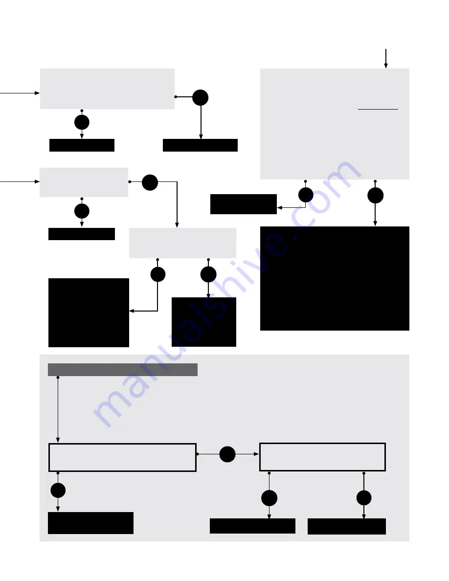
Check to make sure gas pressure is 

within minimum and maximum inputs, as 

indicated on the heater’s rating plate. 

Is the gas pressure OK?

Is the heater properly 

grounded? Is the heater’s 

polarity correct?

Replace gas valve.

Correct problem.

No

Correct problem.

No

On the outside of the control box, is there 

24 V across the ‘W2’ and ‘C’ connectors on 

the terminal strip?

Repair or replace faulty 

wiring or thermostat.

Replace relay board.

No

If heater does not go into high fire mode:

Measure voltage across the ‘HI’ and 

the ‘C’ connectors on the gas valve. 

Is it 24 V?

Yes

No

Yes

Replace gas valve.

NOTE

: To confirm that the heater is not in high fire mode, check manifold pressure.

If manifold pressure is 3.3” to 3.5” for natural gas or 9” to 10” for propane, the light is faulty and should 

be replaced.

When the heater is in low fire mode, manifold pressure is approximately 2.0” to 2.5” for natural gas or  

5.0” to 6.5” for propane.  If this is the case, the following troubleshooting steps should be followed:

Yes


Replace the appropriate pressure switch  

  after verifying: 

•  There is continuity across the thermal fuse.

•  Heater, fan blowers ,squirrel cage, intake 

and exhaust are clean and free from dirt and 

obstructions.

•  The 4” air intake pipe does not exceed 20 ft. 

and/or 2 elbows.

•  There is not a negative pressure experienced 

at the area of air intake (e.g.; high winds, attic 

space, tightly sealed building).

Continued from page 51

The heater is equipped with two safety 

pressure switches. The burner switch is a 

normally open switch and the exhaust switch 

is a normally closed switch. 

Temporarily


place jumpers across the terminals of the 

exhaust switch (reinstall control box cover). 

Does the igniter glow red?  


NOTE

: If normal operation does not continue 

after bypassing the exhaust switch, consult 

factory to troubleshoot the burner switch prior 

to continuing.

Yes

No

With a microampmeter, check 

DC amperage at flame rod. Is it 

greater than .07 microamps?

Check to make 

sure flame sensor 

wire is OK and 

then replace 

circuit board.

Sensing rod is faulty or 

flame is weak. Check 

to make sure heater is 

operating at proper gas 

pressure as indicated on 

heater’s rating plate and 

then, if needed, replace 

sensing rod.

Yes

Yes

No

Replace circuit 

board.

Summary of Contents for LD3-15-40

Page 1: ...indoor living or sleeping quarters etc Installation of a tube heater system in residential indoor living spaces may result in property damage serious injury asphyxiation or death LD3 Series Installat...

Page 2: ...7 Burner Control Box Suspension 19 Reflector Assembly 20 Final Heater Assembly 22 Venting 23 Combustion Air Requirements 30 Separated Combustion Systems 31 Combustion Air Supply Room Air 32 Optional U...

Page 3: ...mber Gas Type select one Maximum Input BTU h Minimum Input BTU h Straight Length U Tube Length Standard Weight lbs Recommended Mounting Height Combustion Chamber Black Coated Radiant Emitter Tube s Bl...

Page 4: ...is heater must be installed and serviced by trained gas installation and service personnel only This is NOT an explosion proof heater DO NOT install in explosive environments Where there is the possib...

Page 5: ...ww drp co com parts Serial No 1311XXXXXXXXXX 0001 Gas Valve Circuit Board Wire Harness N O Switch N O VL Orifice N C Switch N C VL Orifice Diff Switch Diff VL Orifice Igniter Burner 16 Tube Ind Lights...

Page 6: ...RNING Improper installation adjustment alteration service or maintenance can cause property damage serious injury or death Read and understand the installation operation and maintenance instructions t...

Page 7: ...om above the upper surface of wings or of the engine enclosures of the highest aircraft that may be housed in the hangar The measurement shall be made from the wing or engine enclosure whichever is hi...

Page 8: ...Clearances to Combustibles A critical safety factor to consider before installation is the clearances to combustibles Clearance to combustibles is defined as the minimum distance you must have betwee...

Page 9: ...le with 2 Side Shields P N SSE Side Side Below Top Front Behind Below Top Front Behind Below Top Side Side Below Top WARNING Failure to comply with the stated clearances to combustibles may result in...

Page 10: ...ss been evaluated Does the design meet the needs of the space Have recommended mounting heights been observed Have all clearance to combustible situations been observed Is the supply burner end of the...

Page 11: ...12 x 12 20 30 30 50 18 30 ft 50 000 9 14 32 x 15 15 x 15 20 30 30 50 18 Optional protective guard P N PG is required when mounting below 8 feet Factory recommended mounting heights are listed as a gu...

Page 12: ...4 tube hanger TP 19B on the tapered titanium combustion chamber s 4 O D end The spacing between the burner control box mounting brackets and the 4 tube hanger should be 2 4 4 Mark locations for hangi...

Page 13: ...is located on the swaged end of the tube s 3 or 4 Reflector Center Support TP 1078 or TP 82 13 LD3 Series Chart 3 2 Heater Mounting Requirements and Weights Refer to page 18 for U Bend configuration d...

Page 14: ...type of suspension anchor to hanging point 7 IF USING CHAINS Attach and close S hook P N S HOOK and 1 double loop chain P N THCS to anchor Check that it is securely attached NOTE Threaded rod and turn...

Page 15: ...ngle with two suspension points using two optional Brass Knuckle P N BK fittings 1 double loop chains and S hooks U Tubes can be mounted from a single suspension point using an optional Single Mountin...

Page 16: ...ch subsequent tube will utilize one 1 hanger Refer to page 22 for tube installation sequence 2 Slide tube clamps onto radiant tubes see figure 3 7 Figure 3 6 Attach Hangers Figure 3 7 Attach Tube Clam...

Page 17: ...difficult to mate the tubes they may be installed incorrectly 4 Center tube clamps over the seam where two radiant tube sections connect If necessary rotate tube clamps so they will not interfere with...

Page 18: ...4 Overall Dimensions for Heaters Configured With U Bend 180 3 U Bend P N DB TF1B 90 3 Elbow P N DB E6 Tube Length Dimension B Notes 15 ft N A N A 20 ft 13 0 N A 30 ft 17 8 Requires P N LV3 5EA SUB Mo...

Page 19: ...N THCS to anchor Check that it is securely connected 4 Attach chain assemblies and S hooks to mounting brackets on the burner control box Adjust chain lengths until level and in straight alignment wi...

Page 20: ...her using sheet metal screws except at the expansion joint see p 22 NOTE Installer to supply sheet metal screws 4 Attach reflector end caps with polished finish inward to each end of the reflector run...

Page 21: ...downward away from sidewalls and combustibles Protective Guard Used to prevent debris or objects from becoming lodged PG between the radiant tube and reflector Required when mounting heaters below 8 f...

Page 22: ...C B C B NOTE When securing joints on reflectors which are rotated on an angle from horizontal secure joint only on top side of reflector to allow for sufficient heater expansion and contraction 1 to...

Page 23: ...vent pipe should be corrosion resistant galvanized steel of a thickness that meets the National Fuel Gas Code Minimum thickness for connectors varies depending on the pipe diameter Never vent the LD3...

Page 24: ...poisoning or death The following steps shall be followed for each appliance connected to the venting system being placed into operation while all other appliances connected to the venting system are n...

Page 25: ...minimum of 4 feet below 4 feet horizontally from or 1 foot above any window or door that may be opened or gravity air inlet into the building Vent must terminate a minimum of 4 feet above grade level...

Page 26: ...ctures All vertically vented heaters that are Category I must be connected to a chimney or vent complying with a recognized Standard or lined masonry or concrete chimney with a material acceptable to...

Page 27: ...at a pitch of 1 4 inch per foot Vent enclosed spaces and buildings according to the guidelines in this manual and applicable national state provincial and local codes You may either use an agency cert...

Page 28: ...prevent blockage by snow and protect building materials from degradation by flue gases The vent cap must be a minimum of 6 inches from the sidewall of the building Vent must be a minimum of 36 inches...

Page 29: ...alled within the common portion of the vent carrying system reduces the maximum common vent capacity by 10 Refer to NFPA 54 IFEC tables 11 2 and 11 3 for capacity The vent connector capacities allow f...

Page 30: ...es degreasers paints paint removers lubricants pesticides etc are present in the atmosphere High humidity Contaminants such as sawdust welding smoke etc Negative building pressure Unusually tight cons...

Page 31: ...Seal all joints with metallic tape or silicone sealant Wrap the tape two full turns around the vent pipe Slope air intake pipe inch per foot upward or downward away from the unit Do not draw air from...

Page 32: ...n with air infiltration rates of less than 0 40 air changes per hour outside combustion air is typically needed unless the sheer size of the building allows otherwise Contact the factory for further d...

Page 33: ...function simultaneously The minimum clearance between the air intake and the exhaust terminal is 4 feet NOTE When installing in a U Tube configuration use extra caution to separate vent gases from hea...

Page 34: ...uidelines in this manual In the United States refer to the latest edition of the ANSI Z223 1 NFPA 54 Standard and in Canada refer to the latest edition of the CAN CGA B149 1 Standard Supply gas piping...

Page 35: ...latest edition or CSA B149 1 and B149 2 Support all gas piping with pipe hangers metal strapping or other suitable material Do not rely on the heater to support the gas pipe When connecting piping to...

Page 36: ...n a corrosive environment or near corrosive substances use a gas connector suitable for the environment Do not use the gas piping to electrically ground the heater Installation of the Gas Line to the...

Page 37: ...ly pressure from the building main to the inlet of the unit Refer to the chart for the appropriate range of inlet pressures for each gas type When sizing the inlet gas pipe diameter make sure that the...

Page 38: ...inches W C 1 2 PSI Supply pressures greater than 14 W C can damage the controls resulting in personal injury property damage or death WARNING Testing for gas leaks with an open flame or other sources...

Page 39: ...larity must be observed when making field connections Internal Wiring Diagrams Before wiring this appliance check the existing wiring replace if necessary If any of the original wire supplied with the...

Page 40: ...hen plugging in the heater make sure the supply cord is protected from damage and keep all cords away from the heater s surfaces and out of the clearances to combustibles zones see page 9 When routing...

Page 41: ...t Connection with External Relay Kit Thermostat Location The location of the thermostat should be determined by the desired heating requirements and be mounted on an inside wall five 5 feet above the...

Page 42: ...unit is properly grounded as per the National Electrical Code ANSI NFPA 70 or Canadian Electrical code CSA C22 1 Part 1 9 9 The unit is properly mounted to a permanent structure able to bear the weigh...

Page 43: ...the burner This heater cannot be lighted manually Do not try to light the burner by hand Verify minimum inlet gas supply pressure 7 Turn on all other gas appliances that are on the same supply line I...

Page 44: ...on the valve body see Figure 3 30 2 Remove the manifold pressure tap plug on the gas control valve see Figure 3 30 3 Connect the pressure gauge tube and manometer 4 Turn on the gas valve with the swit...

Page 45: ...tap plug on the gas control valve 15 Leak check the re installed pressure tap plug using a soap solution or equivalent method as described in ANSI Z223 1 NFPA 54 Prior to leaving the Job Site Prior to...

Page 46: ...ion above 6 000 ft the input rate will have to be de rated to ensure proper operation The deration is achieved by a gas orifice change Contact the factory for installations above these elevations WARN...

Page 47: ...he lowest setting 3 Turn OFF all electrical power to the appliance 4 Turn manual shutoff clockwise to OFF 5 Wait five 5 minutes to clear out any gas If you smell gas STOP Follow the safety information...

Page 48: ...om the second stage of the thermostat In order for high fire to engage low fire must be energized as well The thermostat determines which stage to maintain for the desired comfort level Shut Down When...

Page 49: ...2 flashes Red Ignitor error 12 seconds 3 flashes Red Gas valve error 4 flashes Red Line voltage frq error 5 flashes Red Internal control error 6 flashes Red Pressure switch error Some LED codes have...

Page 50: ...obstruction or correct vent lengths Replace wiring or hose connections No No No Yes Find source of electrical problem Is the igniter physically damaged No Yes Replace igniter No Check voltage at igni...

Page 51: ...is not a negative pressure experienced at the area of intake e g high winds attic space tightly sealed building No Repair thermostat or thermostat wiring Yes Remove obstruction Is the draft inducer i...

Page 52: ...within 1 2 seconds No Does the burner stay on for approximately 8 10 seconds and then shut off No Yes Turn on gas supply line No Purge gas line No Check inlet pressure and limit switches Check circui...

Page 53: ...followed Yes Replace the appropriate pressure switch after verifying There is continuity across the thermal fuse Heater fan blowers squirrel cage intake and exhaust are clean and free from dirt and ob...

Page 54: ...4 3097A 3044 3098A 3008 3002A 3099A 76 212 1070A 5 3062 3063 826 3001B 3004 3014 3115 3003A 1325 851C 3252 31D 68B 3010 83 3380 3033F 3096A 333 321 217 3093 70A 222 85 828 3094A 84 331 3023 70 245 205...

Page 55: ...105 Reflector End Cap Aluminum TP 3023 Snap in Bushing TP 106 Reflector End Cap Clips TP 3024 8 x 1 2 SMS Point Tip TP 112 5 Reflector Aluminum TP 3029 Thermostat Terminal Board Two Stage TP 113 Refle...

Page 56: ...personnel To check gas tightness of the safety shut off valves turn off the manual valve upstream of the appliance combination control Remove the hex head plug on the inlet side of the combination co...

Page 57: ...ificantly depending on the environment Dirt and dust can be vacuumed or wiped with a soap and water solution Use metal polish if the reflectors are severely dirty Contact service personnel if repairs...

Page 58: ...roit Radiant Products Company has made a diligent effort to provide product information and illustrate the products in this literature accurately however such information and illustrations are for the...

Page 59: ...59 LD3 Series Notes 5 0 Maintenance...

Page 60: ...the maximum permissible stacking height to maintain the required clearances from the heater to the combustibles Signs must either be posted adjacent to the heater thermostats or in the absence of such...

Reviews: