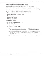
background image

DDDL/SNAPSHOTS

9. If you want to accept the suggested name for the file click once with the left mouse button

on the

Save

option box. You may replace the suggested name by hitting the space bar once

to clear the line. Type in the new file name before saving the file. You may also change
the location of where the file is saved on your PC by changing the location designated
in the

Save In

box. You may save the file to your

A

drive for example. Once the file

has been saved the process is complete.

USING SNAPSHOT REPLAY CONTROLS

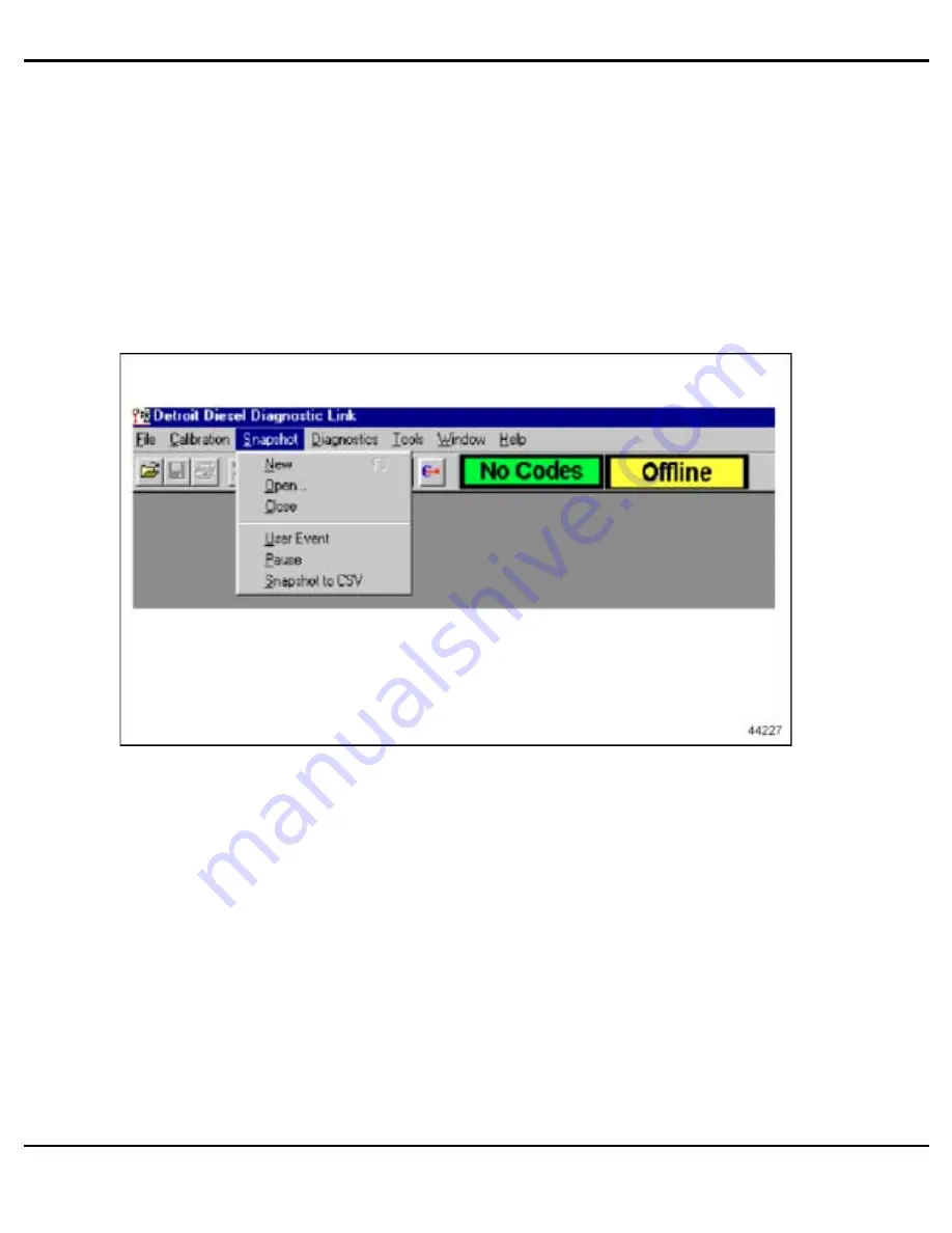
1. To replay a snapshot, go to the

Snapshot

drop-down menu and select

Open

. You should

not be connected to a vehicle when replaying a snapshot.

2. A dialog box will appear listing all the available snapshot files.

6-4

All information subject to change without notice.

(Rev. April 2004)

7SE60 0404

Copyright © 2004 DETROIT DIESEL CORPORATION

Summary of Contents for 60 EGR Series

Page 1: ......

Page 2: ......

Page 3: ...s to be used in conjunction with the DDEC III IV Single ECM Troubleshooting Guide and the DDEC V Single ECM Troubleshooting Guide Series 60 Detroit Diesel DDC DDEC and the spinning arrows design are registered trademarks of Detroit Diesel Corporation Diagnostic Link is a registered trademarks of the Detroit Diesel Corporation ...

Page 4: ......

Page 5: ...llence in products service support and training As products become more and more advanced today s technicians must become specialized in multiple areas This manual is designed with that thought in mind This Series 60 EGR Technician s Guide will provide you with concentrated information that will allow you to excel in EGR technology The Series 60 EGR Technician s Guide covers the October 2002 throu...

Page 6: ...ii All information subject to change without notice Rev April 2004 7SE60 0404 Copyright 2004 DETROIT DIESEL CORPORATION ...
Page 7: ...T EXAMPLES 7 1 8 DDEC V COMPONENTS 8 1 9 DDEC V CODES 9 1 10 DDEC V TESTING 10 1 APPENDIX A LIST OF ACRONYMS A 1 APPENDIX B DDEC IV WIRING SCHEMATICS B 1 APPENDIX C ENGINE DIAGNOSTIC QUESTIONNAIRE C 1 APPENDIX D SERVICE INFORMATION LETTERS D 1 All information subject to change without notice Rev April 2004 iii 7SE60 0404 Copyright 2004 DETROIT DIESEL CORPORATION ...
Page 8: ...TABLE OF CONTENTS iv All information subject to change without notice Rev April 2004 7SE60 0404 Copyright 2004 DETROIT DIESEL CORPORATION ...
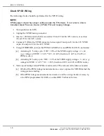
Page 9: ...o properly diagnose and troubleshoot a DDEC IV or DDEC V Series 60 EGR engine is the Detroit Diesel Diagnostic Link DDDL This tool will provide you all the help you will need as it contains proper troubleshooting information for all products NOTE It is absolutely critical that you understand the EGR system to be qualified to offer any type of proper diagnostics Do not waste time trying to troubles...

Page 10: ...ing connectors Check for poor mating of the connector halves or terminals not fully seated in the connector body backed out terminals Look for improperly formed or damaged terminals All connector terminals in the problem circuit should be carefully inspected to determine proper contact tension Use a mating terminal to test the contact tension Check for electrical system interference caused by a de...

Page 11: ...cian Intermittent Problems Talk to the operator driver Be specific Develop your own Driver Questionnaire see Figure 1 1 NOTE A full page copy of the questionnaire can be found in Appendix C All information subject to change without notice Rev April 2004 1 3 7SE60 0404 Copyright 2004 DETROIT DIESEL CORPORATION ...
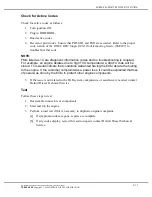
Page 12: ...INTRODUCTION Figure 1 1 Drivers Questionnaire 1 4 All information subject to change without notice Rev April 2004 7SE60 0404 Copyright 2004 DETROIT DIESEL CORPORATION ...
Page 13: ...roblem occurred 4 Does the problem occur only at specific operating conditions If so at what load Is it light medium or heavy 5 Does the problem occur at a specific engine operating temperature If so at what engine temperature 6 Does the problem occur at a specific engine operating altitude If so at what altitude 7 Does the problem occur only when above or below specific outside temperatures In wh...

Page 14: ...rong with the ignition wiring 4 Operate the engine under similar load conditions Check the fuel system for restrictions primary filter and fuel tanks for foreign objects blocking the fuel supply Also check the air system Utilize the DDDL snapshot feature 5 Operate the engine at this temperature while attempting to duplicate the problem Use the snapshot feature on the DDDL 6 If possible troubleshoo...

Page 15: ...he purpose of the EGR system is to reduce engine exhaust gas emissions in accordance with EPA regulations Figure 2 1 EGR System All information subject to change without notice Rev April 2004 2 1 7SE60 0404 Copyright 2004 DETROIT DIESEL CORPORATION ...
Page 16: ...re which reduces NOx nitrogen oxides Figure 2 1 illustrates how components of the EGR system function See Figure 2 2 and Figure 2 3 to familiarize yourself with the EGR components 1 VNT Turbocharger 6 S Pipe 2 Turbo Vane Actuator 7 EGR Valve 3 EGR Valve Actuator 8 EGR Cooler 4 Delta Pressure Sensor 9 High Flow Water Pump 5 EGR Gas Delivery Pipe Figure 2 2 Right Side View 2 2 All information subjec...

Page 17: ...old Air Temperature Sensor 2 EGR Mixer 5 Barometric Pressure Sensor 3 Intake Manifold 6 Intake Manifold Boost Pressure Sensor Figure 2 3 Left Side View All information subject to change without notice Rev April 2004 2 3 7SE60 0404 Copyright 2004 DETROIT DIESEL CORPORATION ...
Page 18: ...hat control the Variable Geometry Turbo VNT and the EGR system The location of the VPODs is application dependent During engine EGR operation the VPOD provides modulated air pressure to the pneumatic actuators which change the VNT vanes and EGR valve positions The VPOD interface with other systems may be viewed in see Figure 2 4 2 4 All information subject to change without notice Rev April 2004 7...

Page 19: ...SERIES 60 EGR TECHNICIAN S GUIDE All information subject to change without notice Rev April 2004 2 5 7SE60 0404 Copyright 2004 DETROIT DIESEL CORPORATION ...
Page 20: ...Away View of the Vanes The results of being able to adjust like this are as follow See Figure 2 5 and see Figure 2 6 Enhanced air fuel ratio during engine acceleration 2 6 All information subject to change without notice Rev April 2004 7SE60 0404 Copyright 2004 DETROIT DIESEL CORPORATION ...
Page 21: ... Engine Operation PWM 7 No air pressure to VNT actuator from the VPOD Minimum exhaust restriction Minimum EGR flow while operating in EGR Mode PWM 50 Regulated air pressure to the VNT actuator from the VPOD Moderate exhaust restriction Increased EGR flow while operating in EGR Mode PWM 90 Maximum regulated air pressure to the VNT actuator from the VPOD Maximum regulated exhaust restriction Maximum...

Page 22: ...the turbine wheel in the turbocharger and out the exhaust system in the traditional way When the valve is open some of the exhaust gas is directed into the EGR cooler through the delivery pipe and into the intake manifold EGR Valve Actuator Figure 2 8 EGR Valve Actuator The EGR valve regulates the EGR flow rate via air pressure input from the VPOD The EGR valve has the following components see Fig...

Page 23: ...ator Bracket 2 Splined Crank Arm 5 Adjustable Linkage 3 Pneumatic Actuator Figure 2 9 EGR Cooler Figure 2 10 EGR Cooler Bar and Fin Design All information subject to change without notice Rev April 2004 2 9 7SE60 0404 Copyright 2004 DETROIT DIESEL CORPORATION ...
Page 24: ...ring the pressure differential across the venturi adjacent to outlet of EGR cooler see Figure 2 11 and see Figure 2 12 and the temperature of the exhaust gases see Figure 2 13 determine precise Mass Flow Rate Measurement The ECM uses the delta pressure and exhaust temperature to determine the rate of EGR flow 2 10 All information subject to change without notice Rev April 2004 7SE60 0404 Copyright...

Page 25: ...Sensor The Delta Pressure Sensor measures the pressure difference across the venturi in the transfer pipe Figure 2 13 EGR Temperature Sensor All information subject to change without notice Rev April 2004 2 11 7SE60 0404 Copyright 2004 DETROIT DIESEL CORPORATION ...
Page 26: ... Figure 2 14 The mixer mixes exhaust gas into the fresh air supply flowing from the charge air cooler Once the air has past the mixer the intake manifold defuses EGR gas evenly to each cylinder Sensors are mounted in the intake manifold to monitor the air temperature and the boost pressure 2 12 All information subject to change without notice Rev April 2004 7SE60 0404 Copyright 2004 DETROIT DIESEL...

Page 27: ... a high flow water pump to improve the coolant flow for added heat dissipation NOTE The high flow water pump is not interchangeable with a non EGR engine All information subject to change without notice Rev April 2004 2 13 7SE60 0404 Copyright 2004 DETROIT DIESEL CORPORATION ...
Page 28: ...COMPONENTS 2 14 All information subject to change without notice Rev April 2004 7SE60 0404 Copyright 2004 DETROIT DIESEL CORPORATION ...
Page 29: ... this operating mode when compared to pre EGR engines EGR Control Mode EGR Control Mode occurs when the DDEC engine sensors are performing normally and all engine parameters are within calibration limits as determined by the sensor readings These readings enable DDEC to accurately control exhaust gas flow Transition from EGR to Boost Transition from EGR to Boost Mode occurs when the engine is gene...

Page 30: ...e 30F conditions the engine will operate in a condensation protection mode EGR is disabled during this mode requiring a slower turbo speed The engine will sound different During this mode of operation the operator will notice a lower boost reading compared to when EGR is active however there is NO reduction of power 3 2 All information subject to change without notice Rev April 2004 7SE60 0404 Cop...

Page 31: ...ngine mode for the Series 60 engine The meaning of each color is defined in the list below Red Exhaust Gas Blue No EGR Flow Green Coolant Flow Yellow Vehicle Air VPODs Orange Cooled Exhaust Gas All information subject to change without notice Rev April 2004 3 3 7SE60 0404 Copyright 2004 DETROIT DIESEL CORPORATION ...
Page 32: ...o EGR flowing through the EGR cooler or delivery pipe VNT vane position controlled by intake manifold boost pressure and limited by the turbocharger speed 3 4 All information subject to change without notice Rev April 2004 7SE60 0404 Copyright 2004 DETROIT DIESEL CORPORATION ...
Page 33: ...ases in the intake manifold EGR Valve Activated by DDEC IV Transition from Boost to EGR Mode Initiation of EGR requires minimum engine speed and boost pressure air flow in order to transition into EGR mode without an abrupt drop in air fuel ratio Once minimum RPM and boost levels are attained the ECM sends a signal via PWM 2 to initiate the valve opening event by providing air pressure to the EGR ...

Page 34: ...R VPOD to the EGR actuator opens the butterfly valve Once the EGR butterfly valve opens the EGR flows through the EGR cooler and into the delivery pipe 3 6 All information subject to change without notice Rev April 2004 7SE60 0404 Copyright 2004 DETROIT DIESEL CORPORATION ...
Page 35: ...rs the EGR cooler at high temperatures and is cooled by the engine coolant system to increase the density of the gas This graphic illustrates coolant flow All information subject to change without notice Rev April 2004 3 7 7SE60 0404 Copyright 2004 DETROIT DIESEL CORPORATION ...
Page 36: ...enturi pressure levels are measured from the two venturi taps or ports The delta pressure measurement in conjunction with the EGR temperature determines the EGR flow rate 3 8 All information subject to change without notice Rev April 2004 7SE60 0404 Copyright 2004 DETROIT DIESEL CORPORATION ...
Page 37: ...trolled via the DDEC PWM 4 to regulate air pressure to change the nozzle vane position within the turbocharger Changes to the vane position either closing or opening result in an increase or decrease to the EGR flow rate All information subject to change without notice Rev April 2004 3 9 7SE60 0404 Copyright 2004 DETROIT DIESEL CORPORATION ...
Page 38: ...MODES 3 10 All information subject to change without notice Rev April 2004 7SE60 0404 Copyright 2004 DETROIT DIESEL CORPORATION ...
Page 39: ...or a specific device The failure can generally be found within the component or wiring for that component Engine Protection Codes Red An engine protection DTC is activated when a engine operating condition exists that can cause immediate damage to the engine and the engine should be shut down until the condition is corrected to prevent additional damage Logic Codes Blue A logic DTC is activated wh...

Page 40: ...flow code 39 will activate Conditions that can cause Code 39 include but are not limited to Plugged EGR cooler EGR valve defective stuck open or closed VPOD defective Differential pressure sensor plugged The DTC will help guide the technician to the condition The technician will require a knowledge of the system and proper tools to diagnose the components 4 2 All information subject to change with...

Page 41: ...age High 22 91 4 Throttle Position Sensor Input Voltage Low 23 174 3 Fuel Temperature Sensor Input Voltage High 24 174 4 Fuel Temperature Sensor Input Voltage Low 25 Reserved for No Codes 26 25 11 Aux Shutdown 1 Active 26 61 11 Aux Shutdown 2 Active 27 105 3 Intake Manifold Temperature Sensor Input Voltage High 27 171 3 Ambient Air Temperature Sensor Input Voltage High 28 105 4 Intake Manifold Tem...

Page 42: ...SRS missing SRS 43 111 1 Coolant Level Low 44 105 0 Intake Manifold Temperature High 44 110 0 Coolant Temperature High 44 172 0 Air Inlet Temperature High 44 175 0 Oil Temperature High 105 14 Inlet Manifold Temperature Derate 110 14 Coolant Temperature Derate 45 100 1 Oil Pressure Low 46 168 1 ECM Battery Voltage Low 46 214 1 RTC Backup Battery Voltage Low 46 232 1 Sensor Supply Voltage Low 47 102...

Page 43: ...utput 6 Short to Battery X3 62 54 4 Aux Output 6 Open Circuit X3 62 54 7 Aux Output 6 Mechanical System Not Responding Properly X3 62 55 3 Aux Output 7 Short to Battery Y3 62 55 4 Aux Output 7 Open Circuit Y3 62 55 7 Aux Output 7 Mechanical System Not Responding Properly Y3 62 56 3 Aux Output 8 Short to Battery A1 62 56 4 Aux Output 8 Open Circuit A1 62 56 7 Aux Output 8 Mechanical System Not Resp...

Page 44: ...ltage Low ESS Transmission 74 70 4 Optimized Idle Safety Loop Short to Ground 74 99 0 Oil Filter Restriction High 75 168 0 ECM Battery Voltage High 75 214 0 RTC Backup Battery Voltage High 75 232 0 Sensor Supply Voltage High 76 121 0 Engine Overspeed With Engine Brake 77 100 0 Engine Oil Pressure High 77 102 1 Turbo Boost Pressure Low 77 108 0 Barometric Pressure High 77 108 1 Barometric Pressure ...

Page 45: ...icates EGR flow requested by DDEC and no EGR flow detected SID 146 FMI 7 will be set by the ECM if the signal from the Delta P sensor and EGR temperature sensor indicate EGR flow is below a minimum allowable flow when the ECM is in EGR Mode for a period greater than 50 seconds Response The CEL will be illuminated and the system will be forced into Boost Mode EGR is Disabled for the remainder of th...

Page 46: ...lta P sensor Plugged Delta P lines Failure Mode SID 146 FMI 12 EGR Leak Boost Jake Indicates No EGR flow requested by DDEC andEGR flow is detected while braking SID 146 FMI 12 will be set by the ECM if the signal from the Delta P sensor and EGR temperature sensor indicate EGR flow is above a maximum allowable flow when the ECM is in Jake Mode for a period greater than 50 seconds Response The CEL w...

Page 47: ...Mode SID 147 FMI 14 EGR Flow Too Low Indicates EGR flow requested by DDEC and insufficient EGR flow detected SID 147 FMI 14 will be set by the ECM if the signal from the Delta P sensor and EGR temperature sensor indicate EGR flow is below a desired flow for a period greater than 50 seconds Response The CEL will illuminate and a fault message will be generated Possible Causes VNT vanes actuator mec...

Page 48: ...CEL will illuminate and a fault message will be generated Possible Causes VNT vanes actuator mechanical failure Turbocharger failure e g damaged or defective compressor turbine wheel Low vehicle air pressure supply Restricted air inlet including filter Low fuel pressure e g restricted fuel supply Exhaust manifold leakage Leaking delivery pipe Defective or leaking VPOD Leaking air system Charge air...

Page 49: ...ater than 50 seconds Response The CEL will illuminate and a fault message will be generated Possible Causes VNT vanes actuator mechanical failure Turbocharger failure e g damaged or defective compressor turbine wheel Restricted air inlet including filter Exhaust manifold leakage EGR valve leakage Delivery pipe leakage Low vehicle air pressure supply Defective or leaking VPOD Leaking air system Cha...

Page 50: ... will be illuminated and the engine will be torque limited to protect the turbocharger and charge air cooler EGR Delta Pressure Sensor Failure Modes PID 411 FMI 3 Voltage High and FMI 4 Voltage Low Response The CEL will be illuminated and the system will be forced into boost mode The engine will be torque limited during this fault EGR Temperature Sensor Failure Modes PID 412 FMI 3 Voltage High and...

Page 51: ...ion Codes When these codes are logged and turn on both the check engine and stop engine lights This alerts the operator that continued engine operation under those conditions will result in engine damage Coolant Temperature High PID 110 FMI 0 indicates the coolant temperature has risen above the programmed value in the ECM The temperature limits are listed in Table 4 2 Oil Pressure Low PID 100 FMI...

Page 52: ...Year Start Derate EGR Off CEL SEL Coolant Temperature 2002 214 F 101 C 221 F 105 C 223 F 106 C 225 F 107 C 2004 219 F 103 C 228 F 108 C 227 F 108 C 229 F 109 C Compressor Discharge Temperatureat Sea Level 2002 453 F 223 C 554 F 290 C 2004 445 F 229 C 515 F 268 C Intake Manifold Temperature 2002 201 F 93 C 213 F 100 C 218 F 103 C 2004 203 F 95 C 216 F 102 C 212 F 100 C Oil Temperature 2002 239 F 11...

Page 53: ...e 5 2 Power Loss Under Heavy Pull Page 5 3 Low Boost Under Cold Ambient Conditions Page 5 4 Derate Codes 110 and 404 FMI 14 Page 5 4 Code 39 Page 5 4 Exhaust Smell Fumes Page 5 5 Slobbering Page 5 5 Engine Vibration Page 5 5 Engine Coolant Loss Page 5 6 Engine Backfire Engine Misfire Intermittent Exhaust Smoke Page 5 6 Testing Procedures Test A Page 5 7 Test B Page 5 8 Exhaust Gas Recirculation Sy...

Page 54: ...he air inlet hoses for soft or collapsed areas a If the air inlet hoses are damaged replace as necessary 4 Visually inspect the air inlet for restrictions a If the air inlet has restrictions clean as necessary 5 Perform Test A Page 5 7 6 Perform Exhaust Gas Recirculation System Basic Checks Page 5 9 7 Test drive the vehicle with DDDL and perform a snapshot Analyze the snapshot 8 Perform Test B Pag...

Page 55: ...rty replace the air filter 3 Visually inspect the air inlet hoses for soft or collapsed areas a If the air inlet hoses are damaged replace as necessary 4 Visually inspect the air inlet for restrictions a If the air inlet has restrictions clean as necessary 5 Visually inspect the entire length of the breather tube for kinks a If the breather tube has kinks repair as necessary 6 Measure the fuel pre...

Page 56: ...ine operating conditions the engine will derate to prevent damage Higher ambient temperatures and loads will increase the frequency of DDEC applying this derate logic If the derate is occurring only occasionally this is Typical If the derate occurs more than Typical for given operating conditions continue investigation for possible defects a If considered Typical clear Fault Codes and return the e...

Page 57: ...raction for excessive idle time Times of 35 and higher are considered excessive 3 Drain the engine lubrication oil pan 4 Refill the lubrication oil pan with 32 quarts of approved motor oil and visually inspect the oil dipstick marking a If the oil dipstick marking is incorrect replace the dipstick with a proper dipstick b If the oil dipstick marking was correct testing is complete Engine Vibration...

Page 58: ...ed perform step 4 4 Visually inspect the engine oil for coolant a Coolant is found in the engine oil this indicates an oil cooler or internal engine fault b If no coolant is found perform step 4 c c If the engine is losing coolant at a rate of more than 1 gallon in in 5000 miles and no engine coolant leaks were detected replace the EGR cooler d If the engine is losing coolant at a rate of less tha...

Page 59: ...leaks b If the pressure is at 27 psi or higher continue to step 4 4 Activate EGR VPOD PWM 2 using the DDDL 5 Monitor the boost psi pressure for pressure drops when the EGR valve opens NOTE The pressure should have dropped significantly to approximately 9 psi a If the air pressure dropped to 9 psi no further testing is required and Test A has been completed b If the pressure only dropped slightly p...

Page 60: ...hot If a dynamometer is not available run the engine until hot 170 F 76 C coolant temperature 2 Activate the VPOD outputs to 90 and back to 7 using the DDDL Visually inspect the VNT and EGR valve for proper rod travel full travel to stops a If the VNT is not functioning properly verify VNT vanes are moving freely read Service Information Letter 03 TS 44 located in Appendix D b If the EGR valve is ...

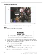
Page 61: ...gage 0 100 psi Check Delta P Sensor Follow these steps to check the Delta P sensor 1 Turn ignition ON 2 Plug in DDR DDDL 3 Read Delta P counts EGR DPS a If Delta P counts read 86 135 verify that the EGR pipes and hoses are correctly assembled from the EGR tube to the Delta P sensor Reversed hoses or pipes will create black smoke and surging Go to step 3 b b Also inspect carefully for split or leak...

Page 62: ...stall pressure gauges accurate to within 1 4 kPa 0 2 psi at the outlet of the EGR and VNT hoses Use two gauges or test separately 3 Using the DDR DDDL activate PWM 2 EGR and PWM 4 VNT duty cycles and monitor the output pressure from the VPOD 4 Test activating 11 duty cycle Pressure 106 134 kPa 15 4 19 4 psi Go to steps 5 a and 5 b 5 Test activating 90 duty cycle Pressure 485 515 kPa 70 75 psi a If...

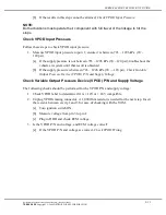
Page 63: ...ck Variable Output Pressure Device VPOD P N and Supply Voltage Check Variable Output Pressure Device VPOD P N and Supply Voltage The following checks should be performed for the VPOD P N and supply voltage 1 Check VPOD label to determine if it is 12V or 24V compatible 2 Unplug VPODs mating connector A 1 000 Ohm resistor is needed for the next step Insert the resistor between cavity 1 and 3 for eas...

Page 64: ...e and PWM 4 VNT and ensure a Activating 11 duty cycle VDC 90 of the VPOD supply voltage 1 volt e g voltage to VPOD 13 8V 0 9 12 42V therefore 11 42V to 13 42V at PWM is okay b Activating 90 duty cycle VDC 10 of the VPOD supply voltage 1 volt e g voltage to VPOD 13 8V 0 1 1 38V therefore 0 38V to 2 38V at PWM is okay 6 Note any air leakage when PWMs are activated to 90 and correct the leaks as need...

Page 65: ...anted having the ECM derate the fueling to the engine If the customer complaint was a power loss it could be explained that loss of power was done by the ECM to protect other engine components 5 If the issue is not related to the EGR system components or assistance is needed contact Detroit Diesel Technical Service Test Follow these steps to test 1 Reassemble connectors or components 2 Start and r...

Page 66: ...DDEC IV TESTING 5 14 All information subject to change without notice Rev April 2004 7SE60 0404 Copyright 2004 DETROIT DIESEL CORPORATION ...
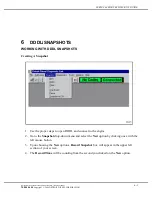
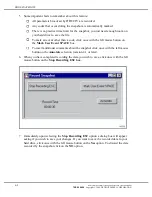
Page 67: ...down menu and select the New option by clicking once with the left mouse button 3 Upon choosing the New option a Record Snapshot box will appear in the upper left section of your screen 4 The Record Time will be counting from the second you clicked on the New option All information subject to change without notice Rev April 2004 6 1 7SE60 0404 Copyright 2004 DETROIT DIESEL CORPORATION ...
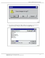
Page 68: ...pshot click once with the left mouse button on the Annotate selection version 4 1 or later 6 When you have completed recording the data you wish to save click once with the left mouse button on the Stop Recording ESC box 7 Immediately upon selecting the Stop Recording ESC option a dialog box will appear asking if you wish to save your changes If you want to save the recorded data to your hard driv...

Page 69: ... Yes option the Save As dialog box will appear on your screen A suggested file name will appear outlined in blue in the File Name box All information subject to change without notice Rev April 2004 6 3 7SE60 0404 Copyright 2004 DETROIT DIESEL CORPORATION ...
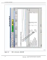
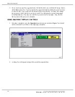
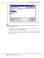
Page 70: ...n your PC by changing the location designated in the Save In box You may save the file to your A drive for example Once the file has been saved the process is complete USING SNAPSHOT REPLAY CONTROLS 1 To replay a snapshot go to the Snapshot drop down menu and select Open You should not be connected to a vehicle when replaying a snapshot 2 A dialog box will appear listing all the available snapshot...

Page 71: ...k of the left mouse button The selected file name will now appear in the File Name box 4 Click once with the left mouse button on the Open box in the lower right of the dialog box 5 When you have opened a snapshot replay controls will appear at the bottom of the DDDL window you opened All information subject to change without notice Rev April 2004 6 5 7SE60 0404 Copyright 2004 DETROIT DIESEL CORPO...

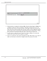
Page 72: ...ts current position and the instruments show the appropriate readings The event window also changes during the replay to show the most recent event 7 Stop the replay at a particular point of interest by clicking on Pause The instruments will show the values at the time the replay was stopped 8 Move to a specific time in the replay by dragging the replay slider button As you drag the slider the tim...

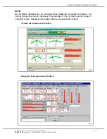
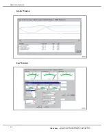
Page 73: ...t access the injector response time window or the cylinder cutout window in snapshot mode Samples of windows that may be activated include Normal Instrumentation Window Diagnostic Instrumentation Window All information subject to change without notice Rev April 2004 6 7 7SE60 0404 Copyright 2004 DETROIT DIESEL CORPORATION ...
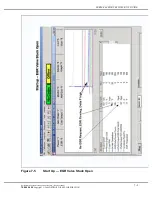
Page 74: ...DDDL SNAPSHOTS Graph Window User Window 6 8 All information subject to change without notice Rev April 2004 7SE60 0404 Copyright 2004 DETROIT DIESEL CORPORATION ...

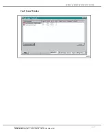
Page 75: ...SERIES 60 EGR TECHNICIAN S GUIDE Fault Codes Window All information subject to change without notice Rev April 2004 6 9 7SE60 0404 Copyright 2004 DETROIT DIESEL CORPORATION ...

Page 76: ...DDDL SNAPSHOTS 6 10 All information subject to change without notice Rev April 2004 7SE60 0404 Copyright 2004 DETROIT DIESEL CORPORATION ...

Page 77: ...gure 7 2 Throttling without load EGR is on and off See Figure 7 3 1500 rpm throttling no EGR See Figure 7 4 EGR Valve stuck open See Figure 7 5 147 14 EGR Flow too Low See Figure 7 6 146 2 EGR leak boost See Figure 7 7 Leaking Charge Air Cooler See Figure 7 8 Delta P port plugged graph See Figure 7 9 Normal Acceleration Automatic Transmission See Figure 7 10 Typical EGR flow loaded See Figure 7 11...

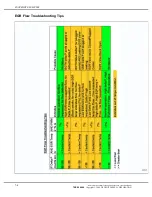
Page 78: ...r leaking includes sensor mounting o rings The sensor being defective is the least likely Incorrectly wired replacement sensor Low Delta P with Flow Demand PWM2 greater than 7 and less than 90 If the EGR valve is open and the EGR temperature is elevated there should EGR flow If the Delta P sensor is registering a low differential pressure in this condition it is likely that the pressure signal to ...

Page 79: ...respond to the false signal VPOD The Variable Pressure Orfice or Output Device is used to control the pressure to the actuators used for the EGR valve and turbocharger vane position The most common failure is external leakage of air You can hear the leak when you activate the PWM for each VPOD Relative Humidity Turbo Compressor Inlet Temperature Sensor This sensor is a DDC part installed and wired...

Page 80: ...SNAPSHOT EXAMPLES EGR Flow Troubleshooting Tips 7 4 All information subject to change without notice Rev April 2004 7SE60 0404 Copyright 2004 DETROIT DIESEL CORPORATION ...

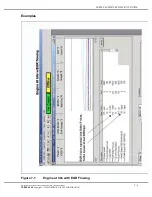
Page 81: ...RIES 60 EGR TECHNICIAN S GUIDE Examples Figure 7 1 Engine at Idle with EGR Flowing All information subject to change without notice Rev April 2004 7 5 7SE60 0404 Copyright 2004 DETROIT DIESEL CORPORATION ...

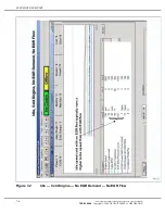
Page 82: ...SNAPSHOT EXAMPLES Figure 7 2 Idle Cold Engine No EGR Demand No EGR Flow 7 6 All information subject to change without notice Rev April 2004 7SE60 0404 Copyright 2004 DETROIT DIESEL CORPORATION ...

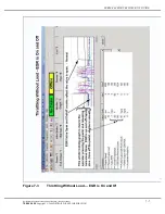
Page 83: ...RIES 60 EGR TECHNICIAN S GUIDE Figure 7 3 Throttling Without Load EGR is On and Of All information subject to change without notice Rev April 2004 7 7 7SE60 0404 Copyright 2004 DETROIT DIESEL CORPORATION ...

Page 84: ...SNAPSHOT EXAMPLES Figure 7 4 1500 No Load EGR Off 7 8 All information subject to change without notice Rev April 2004 7SE60 0404 Copyright 2004 DETROIT DIESEL CORPORATION ...

Page 85: ...SERIES 60 EGR TECHNICIAN S GUIDE Figure 7 5 Start Up EGR Valve Stuck Open All information subject to change without notice Rev April 2004 7 9 7SE60 0404 Copyright 2004 DETROIT DIESEL CORPORATION ...

Page 86: ...SNAPSHOT EXAMPLES Figure 7 6 Code 147 14 EGR Flow Too Low 7 10 All information subject to change without notice Rev April 2004 7SE60 0404 Copyright 2004 DETROIT DIESEL CORPORATION ...

Page 87: ...SERIES 60 EGR TECHNICIAN S GUIDE Figure 7 7 146 2 EGR Leak Boost Power All information subject to change without notice Rev April 2004 7 11 7SE60 0404 Copyright 2004 DETROIT DIESEL CORPORATION ...

Page 88: ...SNAPSHOT EXAMPLES Figure 7 8 Leaking Charge Air Cooler 7 12 All information subject to change without notice Rev April 2004 7SE60 0404 Copyright 2004 DETROIT DIESEL CORPORATION ...

Page 89: ... EGR TECHNICIAN S GUIDE Figure 7 9 One of the Delta P Ports Plugged in the Delivery Pipe All information subject to change without notice Rev April 2004 7 13 7SE60 0404 Copyright 2004 DETROIT DIESEL CORPORATION ...

Page 90: ...SNAPSHOT EXAMPLES Figure 7 10 Normal Operation Eaton Autoshift Transmission 7 14 All information subject to change without notice Rev April 2004 7SE60 0404 Copyright 2004 DETROIT DIESEL CORPORATION ...

Page 91: ...SERIES 60 EGR TECHNICIAN S GUIDE Figure 7 11 Normal EGR Flow with Request All information subject to change without notice Rev April 2004 7 15 7SE60 0404 Copyright 2004 DETROIT DIESEL CORPORATION ...

Page 92: ...SNAPSHOT EXAMPLES Figure 7 12 Normal EGR Off 7 16 All information subject to change without notice Rev April 2004 7SE60 0404 Copyright 2004 DETROIT DIESEL CORPORATION ...

Page 93: ...SERIES 60 EGR TECHNICIAN S GUIDE Figure 7 13 Plugged Delta P Port All information subject to change without notice Rev April 2004 7 17 7SE60 0404 Copyright 2004 DETROIT DIESEL CORPORATION ...

Page 94: ...SNAPSHOT EXAMPLES 7 18 All information subject to change without notice Rev April 2004 7SE60 0404 Copyright 2004 DETROIT DIESEL CORPORATION ...

Page 95: ...sign Enhanced DDEC ECU Hydraulic actuated EGR Valve Tube and Shell EGR Cooler NOTE DDDL software Level 6 0 and higher will be the primary diagnostic tool A diagnostic tool which is not PC supported will not have the ability to diagnose a DDEC V ECU All information subject to change without notice Rev April 2004 8 1 7SE60 0404 Copyright 2004 DETROIT DIESEL CORPORATION ...

Page 96: ... and Output Pins up to 136 vs 81 More flexible inputs 57 Analog channels vs 19 Analog 12 Digital in DDEC IV Up to 27 of these input channels can be configured as Digital inputs Frequency inputs 6 vs 4 Digital outputs 19 8 Hi 11 Lo vs 10 2 Hi 8 Lo PWM outputs 6 vs 4 Lo side Has full support for J1587 and J1939 Data Links 8 2 All information subject to change without notice Rev April 2004 7SE60 0404...

Page 97: ... security and reprogramming flexibility Proven reliability and durability that customers demand Easily accessible components reducing maintenance time and simplifying troubleshooting Integrated engine protection features with lights for visual awareness Easily retrievable historical fault codes for diagnostic capability Operating statistics are tracked fuel consumed miles traveled hours used for a...

Page 98: ...hydraulically actuated valve that operates on engine oil instead of air This design feature eliminates the need for an EGR VPOD The butterfly valve design is still used to control the exhaust gas flow See Figure 8 2 8 4 All information subject to change without notice Rev April 2004 7SE60 0404 Copyright 2004 DETROIT DIESEL CORPORATION ...

Page 99: ...d Shell EGR Cooler The new EGR Cooler features a durable tube shell core and a cast housing that have less weld joints than the previous design See Figure 8 3 All information subject to change without notice Rev April 2004 8 5 7SE60 0404 Copyright 2004 DETROIT DIESEL CORPORATION ...

Page 100: ...DDEC V COMPONENTS 8 6 All information subject to change without notice Rev April 2004 7SE60 0404 Copyright 2004 DETROIT DIESEL CORPORATION ...

Page 101: ...evel Sensor Input Voltage Low 13 146 6 EGR Valve Current Too High 14 110 3 Coolant Temperature Sensor Input Voltage High 14 175 3 Oil Temperature Sensor Input Voltage High 15 110 4 Coolant Temperature Sensor Input Voltage Low 15 175 4 Oil Temperature Sensor Input Voltage Low 16 111 3 Coolant Level Sensor Input Voltage High 16 111 5 Add Coolant Level Sensor Input Voltage High 16 146 5 EGR Valve Cur...

Page 102: ...61 3 Aux Output 13 E47 Open Circuit High Side 31 261 4 Aux Output 13 E47 Short To Ground High Side 31 261 7 Aux Output 13 E47 Mechanical System Failure 31 262 3 Aux Output 14 E50 Open Circuit High Side 31 262 4 Aux Output 14 E50 Short To Ground High Side 31 262 7 Aux Output 14 E50 Mechanical System Failure High Side 31 263 3 Aux Output 15 E51 Open Circuit High Side 31 263 4 Aux Output 15 E51 Short...

Page 103: ...old Temperature 44 110 0 Coolant Temperature High 44 110 14 Engine Power Derate Due To Coolant Temperature 44 172 0 Air Inlet Temperature High 44 175 0 Oil Temperature High 44 175 14 Oil Temperature Derate 45 100 1 Oil Pressure Low 46 155 4 Injector Vreg Voltage Failed Low 46 168 1 ECU Battery Voltage Low 46 211 1 Vehicle Sensor Supply Voltage Low 46 212 4 Injector Vslope Voltage Failed Low 46 214...

Page 104: ...iled 58 92 0 Torque Overload 58 216 7 ECU Information Not Responding Mux d Dashboard Devices 58 242 9 Cruise Control Resume Accel Switch Not Responding 58 242 12 Cruise Control Resume Accel Switch Failed 58 243 9 Cruise Control Set Coast Switch Not Responding 58 243 12 Cruise Control Set Coast Switch Failed 58 244 9 Cruise Control Enable Switch Not Responding 58 244 12 Cruise Control Enable Switch...

Page 105: ...echanical System Not Responding Properly V53 62 250 12 J1587 Data Link Fault 62 257 3 Aux Output 9 V54 Short To Battery 62 257 4 Aux Output 9 V54 Open Circuit 62 257 7 Aux Output 9 V54 Mechanical System Failure Pin Top 2 62 258 3 Aux Output 10 V55 Short To Battery 62 258 4 Aux Output 10 V55 Open Circuit 62 258 7 Aux Output 10 V55 Mechanical System Failure Top 2 62 259 3 Aux Output 11 E13 Short To ...

Page 106: ...eriod 65 107 3 Air Filter Restriction Sensor Voltage High 65 107 4 Air Filter Restriction Sensor Voltage Low 66 99 3 Oil Filter Restriction Sensor Voltage High 66 99 4 Oil Filter Restriction Sensor Voltage Low 67 106 3 Air Inlet Pressure Sensor Input Voltage High 67 106 4 Air Inlet Pressure Sensor Input Voltage Low 67 109 3 Coolant Pressure Circuit Failed High 67 109 4 Coolant Pressure Circuit Fai...

Page 107: ... Barometric Pressure High 77 108 1 Barometric Pressure Low 77 109 0 Coolant Pressure High 77 110 1 Coolant Temperature Low 77 111 0 Coolant Level High 77 151 11 Service Now Lamp Fault Expiration 77 171 0 Ambient Air Temperature High 77 171 1 Ambient Air Temperature Low 77 172 1 Air Inlet Temperature Low 77 174 0 Fuel Temperature High 77 174 1 Fuel Temperature Low 77 175 1 Engine Oil Temperature Lo...

Page 108: ...Pressure High 83 412 0 EGR Temperature High 84 98 1 Oil Level Low 84 355 1 Change Oil Soon 85 190 0 Engine Overspeed 85 190 14 Engine Overspeed Signal 86 73 3 Aux Pump Pressure Sensor Input Voltage High 86 108 3 Barometric Pressure Sensor Input Voltage High 87 73 4 Pump Pressure Sensor Input Voltage Low 87 108 4 Barometric Pressure Sensor Input Voltage Low 89 95 0 Fuel Filter Restriction High 89 1...

Page 109: ...l valve coil 3 Measure the coil resistance between pins A and B Table 9 2 and see Figure 9 1 a If the coil resistance is to low replace the actuator assembly b If the coil resistance is okay go to step 4 4 Disconnect engine harness at ECU and at coil and measure resistance across the two pin connector pins a If resistance is less than 100 the two wires are shorted to each other b If the resistance...

Page 110: ...e solenoid NOTE This symptom may be improved with reprogramming Reprogram the ECU if the ECU has not been reprogrammed since the dates listed below 12 L 02 23 04 14 L 03 08 04 NOTE There is an update program for the DDEC V troubleshooting in 6 0 DDDL 1 a 12L engine b If the software level is below XX on a 14L engine 9 10 All information subject to change without notice Rev April 2004 7SE60 0404 Co...

Page 111: ...I 5 6 EGR Valve Current is too low FMI 5 or EGR Valve Current is too high FMI 6 The CEL AWL will be illuminated and the engine will operate in boost mode All information subject to change without notice Rev April 2004 9 11 7SE60 0404 Copyright 2004 DETROIT DIESEL CORPORATION ...

Page 112: ...DDEC V CODES 9 12 All information subject to change without notice Rev April 2004 7SE60 0404 Copyright 2004 DETROIT DIESEL CORPORATION ...

Page 113: ...t known 2004 DDEC V issues can be resolved by reprogramming the ECU Flash Code 13 and 16 EGR Valve Current Cold engine Idle Smoke Misfire Shutter at Road Speed All information subject to change without notice Rev April 2004 10 1 7SE60 0404 Copyright 2004 DETROIT DIESEL CORPORATION ...

Page 114: ...DDEC V TESTING 10 2 All information subject to change without notice Rev April 2004 7SE60 0404 Copyright 2004 DETROIT DIESEL CORPORATION ...

Page 115: ... Failure Mode Indentifier KRPM RPM X 1000 kPa Kilopascals PID Parameter Identification PSI Pounds per Square Inch PWM Pulse Width Modulation RHS Relative Humidity Sensor RPM Revolutions per Minute SAE Society of Automotive Engineers SEL Stop Engine Light SID System Identification S Pipe Pipe Shaped Like an S VGT Variable Geometry Turbocharger aka VNT VNT Variable Nozzle Turbocharger aka VGT VOM Vo...

Page 116: ...APPENDIX A LIST OF ACRONYMS A 2 All information subject to change without notice Rev April 2004 7SE60 0404 Copyright 2004 DETROIT DIESEL CORPORATION ...

Page 117: ...ehicle Harness see Figure B 1 DDEC IV Engine Wiring Diagram See Figure B 2 DDEC V Engine Harness see Figure B 3 DDEC V Vehicle Interface Harness see Figure B 4 All information subject to change without notice Rev April 2004 B 1 7SE60 0404 Copyright 2004 DETROIT DIESEL CORPORATION ...

Page 118: ...APPENDIX B DDEC IV WIRING SCHEMATICS B 2 All information subject to change without notice Rev April 2004 7SE60 0404 Copyright 2004 DETROIT DIESEL CORPORATION ...

Page 119: ......

Page 120: ......

Page 121: ......

Page 122: ......

Page 123: ... TECHNICIAN S GUIDE APPENDIX C ENGINE DIAGNOSTIC QUESTIONNAIRE Engine Diagnostic Questionnaire All information subject to change without notice Rev April 2004 C 1 7SE60 0404 Copyright 2004 DETROIT DIESEL CORPORATION ...

Page 124: ...APPENDIX C ENGINE DIAGNOSTIC QUESTIONNAIRE C 2 All information subject to change without notice Rev April 2004 7SE60 0404 Copyright 2004 DETROIT DIESEL CORPORATION ...

Page 125: ......

Page 126: ......

Page 127: ...ce Information Letter View One of Four see Figure D 4 Service Information Letter View Two of Four see Figure D 5 Service Information Letter View Three of Four see Figure D 6 Service Information Letter View Four of Four see Figure D 7 Service Information Letter View One of One see Figure D 8 All information subject to change without notice Rev April 2004 D 1 7SE60 0404 Copyright 2004 DETROIT DIESEL...

Page 128: ...APPENDIX D SERVICE INFORMATION LETTERS D 2 All information subject to change without notice Rev April 2004 7SE60 0404 Copyright 2004 DETROIT DIESEL CORPORATION ...

Page 129: ......

Page 130: ......

Page 131: ......

Page 132: ......

Page 133: ......

Page 134: ......

Page 135: ...D 8 S i I f ti L tt 04 TS 17 Vi O f O ...

Reviews: