background image

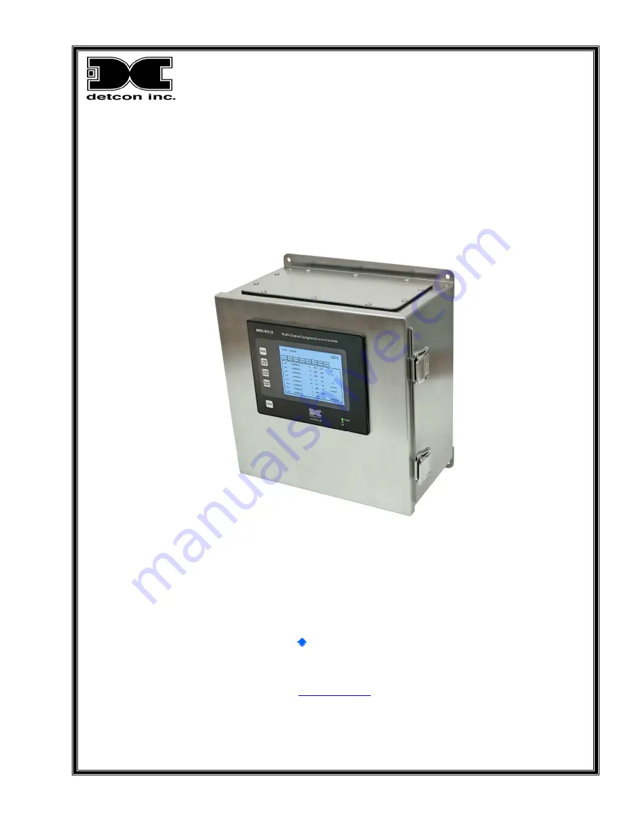
Model MCX-32-N1P

Model MCX-32-N4X

Gas Detection Controller

Operator’s Installation and Instruction Manual

Covers all Model MCX-32 Control Systems

DETCON, Inc.

4055 Technology Forest Blvd.,

The Woodlands, Texas 77381

Ph.281.367.4100 / Fax 281.298.2868

www.detcon.com

February 15, 2013 • Document #3624 • Revision 2.3

Summary of Contents for MCX-32-N1P

Page 1: ...troller Operator s Installation and Instruction Manual Covers all Model MCX 32 Control Systems DETCON Inc 4055 Technology Forest Blvd The Woodlands Texas 77381 Ph 281 367 4100 Fax 281 298 2868 www det...

Page 2: ...Model MCX 32 Model MCX 32 Instruction Manual ii This page left intentionally blank...

Page 3: ...4 7 4 2 Dry Contact Inputs DI 4 9 4 3 Analog 4 20mA Outputs AO 4 10 4 4 Alarm Relay Outputs RL 4 12 4 4 1 Energized or De Energized 13 4 4 2 Silenceable or Non Silenceable 13 4 4 3 Latching or Non La...

Page 4: ...AC DC Inputs 5 Figure 3 MCX 32 N4X Controller Mounting and Dimensional View 5 Figure 4 RS 485 Wiring Terminals for PORT1 PORT2 and REMOTE 7 Figure 5 Model DA 4 4 20mA Input Module and 4 20mA Gas Senso...

Page 5: ...30 Figure 34 Channel Details Screen 31 Figure 35 Channel Description Entry 31 Figure 36 Gas Units Entry 32 Figure 37 Change Range Entry 33 Figure 38 Device Type Selection 33 Figure 39 Alarm Level Set...

Page 6: ...Shipping Address 4055 Technology Forest Blvd The Woodlands Texas 77381 Mailing Address P O Box 8067 The Woodlands Texas 77387 8067 Phone 888 367 4286 281 367 4100 Fax 281 292 2860 www detcon com sale...

Page 7: ...t displays the status of every sensor with more detailed information available by touching the screen Typical sensor status includes channel number tag name gas type concentration and alarm fault stat...

Page 8: ...for all other Modbus devices that are used 1 2 1 Interface PCA The Interface PCA is the primary support for the touch screen controller This PCA is the interface between the Touch Screen Controller s...

Page 9: ...ry 24VDC input the Interface PCA has the unique ability to provide a nominal 27VDC at about 1Amp specifically for charging the batteries This voltage is only to be used for charging batteries Damage m...

Page 10: ...ply is available for the MCX 32 N1P that converts 110 220VAC to 24VDC up to 5Amps and can power up to 32 sensors and any associated I O modules The MCX 32 controller can also be powered by an external...

Page 11: ...e necessary battery charging voltage to the batteries See Section 6 3 9 Power Management Screen for setting up the charging voltage for the batteries NOTE The supply of power should be from an isolate...

Page 12: ...the load 120 Watts 24VDC This voltage can come from an external 24VDC supply or a battery back up If batteries are directly connected to this input the unit has the ability to provide the necessary ba...

Page 13: ...connection to a remote display Figure 4 If a remote display is included in the system configuration connect the RS 485 cable from the Remote Display to these terminals 4 1 Analog 4 20mA Sensor Inputs...

Page 14: ...4 DI 4 Modbus Addresses Port Module Channel Decimal Hex Module Channel Decimal Hex 1 1 1 2 3 4 64 40 2 5 6 7 8 65 41 3 9 10 11 12 66 42 4 13 14 15 16 67 43 5 17 18 19 20 68 44 6 21 22 23 24 69 45 7 2...

Page 15: ...fied to reflect the correct sensor type and information Setting up a DA 4 should start by selecting the Device Type from the Channel Details screen and selecting Model DA4 from the DEVICE SELECTION sc...

Page 16: ...ntroller will display COMM ERR in the Status field A properly addressed DI 4 that is correctly connected to the controller will respond to channel activation with a mA reading When the controller has...

Page 17: ...on its output 3 Figure 8 corresponding to channel 39 s reading Table 2 AO 4 Modbus Addresses Port Module Channel Decimal Hex Module Channel Decimal Hex 1 1 1 2 3 4 160 A0 2 5 6 7 8 161 A1 3 9 10 11 1...

Page 18: ...the controller NOTE The current ratings of the relay contacts should not be exceeded 5A 30VDC 5A 250VAC RELAY COMM M S D L S D Alarm 1 Alarm 2 Alarm 3 Fault Relay 4 Relay 3 Relay 1 Relay 2 There are f...

Page 19: ...with an alarm output related to the alarm set points of the associated channel NOTE RL 4 modules can be connected to either Port 1 or Port 2 they must be addressed correctly they must be defined in B...

Page 20: ...ale connector Plug the male connector into the side of the module Slide it all the way to the end stop Add additional modules next to the first module When installing additional I O modules make sure...

Page 21: ...2 If the Controller has only serial sensors connected a System Auto Configuration can be performed This can be accomplished by entering the Menu and selecting AUTO CONFIGURE SYSTEM This will initiate...

Page 22: ...tial Start Up The MCX 32 controller will power up as soon as power is applied There is no external power switch to the unit NOTE Before applying power check to make sure that all the wiring connection...

Page 23: ...ea Each of these tabs displays information for eight channels Touching one of these tabs will cause the screen to display the eight channels associated with that tab In normal operation the screen wil...

Page 24: ...he MCX 32 controller incorporates password protection to keep un authorized personnel from inadvertently changing the controller s configuration If not already logged in pressing the MENU button will...

Page 25: ...er NOTE The Sensor Life field is applicable for 100 600D and 700 Series sensors This field is not applicable for other device types and the field will display N A In order to make changes to certain v...

Page 26: ...ormation on the sensor type If the device is a Detcon series sensor the controller will obtain configuration information from that sensor and store the information This information can be viewed on th...

Page 27: ...ler utilizes two RS 485 Ports These ports are virtually identical but RL 4 banks must be assigned to either port 1 or port 2 and the RL 4 modules themselves must be connected to the port that their ba...

Page 28: ...ggle that field between the two selections Refer to Section 4 4 Alarm Relay Outputs RL 4 for more information on these settings NOTE There are three banks of alarm relays The bank of relays that a spe...

Page 29: ...assword and then re type that new password The user will then select the CHANGE PASSWORD button and if the new password and the re typed password are the same the new password will take effect and wil...

Page 30: ...the test cycle by selecting the ALARM TEST MODE menu button again As the readings cross their respective ALM1 ALM2 and ALM3 set points the relays will fire according to their configuration Figure 22...

Page 31: ...s 64 channel addresses displaying 8 addresses per page and the Modbus address will be shown as a decimal value The RL4 Diagnostics menu button will display information associated with the controller s...

Page 32: ...lay screen will show that the alarm inhibit function is on by displaying ALARM INHIBIT at the top of the screen along with the active counter NOTE From the Alarm Inhibit screen the controller will ret...

Page 33: ...charging circuitry and apply the charging voltage to the auxiliary 24VDC input terminals NOTE The battery charging feature should not be enabled for external 24VDC power sources or battery backup unit...

Page 34: ...mpact Flash CF card if one is installed The user can also reset delete data logging files and save load controller configurations from this screen This screen Figure 30 is displayed by selecting the C...

Page 35: ...recorded events of a specific date in increments of 10 or 100 by selecting the buttons on the right of the screen accordingly The user can also page back and forth to different dates by selecting the...

Page 36: ...the correct port before they can be utilized Four basic areas need to be configured The number of sensors must be determined before setup begins and configured on the Turn ON OFF Channels screen or an...

Page 37: ...the Modbus If a sensor is located the controller will populate that channel with the information obtained from the sensor 2 The sensor device can be input manually by selecting the Device Type This wi...

Page 38: ...nicate with a sensor or I O Module connected to the channel This is useful if the sensor is not working properly and needs to be removed from being polled Note that the channel is not actually removed...

Page 39: ...ensor this field will display Model 700 as the default value To change the device type select the Device Type field and select the correct type of sensor or I O module If the sensor is connected to a...

Page 40: ...ascending For sensors that are connected via a DA 4 or DI 4 module these set points are default values selected by the controller These set point values should be checked and changed if they are not...

Page 41: ...to the configuration by daisy chaining the remote displays To daisy chain remote displays connect the next remote display in the chain to the slave RS 485 port of the remote display before it in the...

Page 42: ...screen for approximately ten seconds and will then move to the next eight channels If there are any alarms active the screen will remain on the display with the channel that is in alarm If more than...

Page 43: ...sors current concentration the current sensor condition the range of the sensor the gas type the sensor type and if the channel is on or off Some of these fields are changeable on this screen includin...

Page 44: ...urrent Password New Password and Retype New Password Passwords are case sensitive After successfully inputting the current password the operator may enter a new password and then retype that new passw...

Page 45: ...lay is critical for proper operation The setup must match the setup in the MCX 32 Controller for proper operation Two basic areas need to be configured The number of sensors must be entered on the rem...

Page 46: ...ting any device that may be on the RS 485 Modbus Network always refer to that devices manual for proper setup of the device on the network and refer to that manual s troubleshooting section for possib...

Page 47: ...ugged into each other communication with other RS 485 devices will not be possible 4 Connect a working slave device directly to the output terminal blocks of the appropriate port Make sure that it is...

Page 48: ...ce without charge any such equipment found to be defective during the warranty period Full determination of the nature of and responsibility for defective or damaged equipment will be made by Detcon I...

Page 49: ...1 Full Scale AO 4 1 Full Scale Power Input 110 230VAC 20 30VDC Power Consumption Base MCX 32 Controller 20 Watts at 24VDC Total Power consumption is dependent on number of I O modules number of gas se...

Page 50: ...103 6 7 146 9 2 189 B D 232 E 8 18 1 2 61 3 D 104 6 8 147 9 3 190 B E 233 E 9 19 1 3 62 3 E 105 6 9 148 9 4 191 B F 234 E A 20 1 4 63 3 F 106 6 A 149 9 5 192 C 0 235 E B 21 1 5 64 4 0 107 6 B 150 9 6...

Page 51: ...atus 40055 Status 40099 Status 40012 7 Reading 40056 29 Reading 40100 51 Reading 40013 Status 40057 Status 40101 Status 40014 8 Reading 40058 30 Reading 40102 52 Reading 40015 Status 40059 Status 4010...

Page 52: ...Alarm 1 0 No Alarm 1 In alarm 1 Bit 1 Alarm 2 0 No Alarm 1 In alarm 2 Bit 2 Alarm 3 0 No Alarm 1 In alarm 3 Bit 3 Fault 0 No Fault 1 Sensor Fault Bit 4 Cal 0 Normal Operation 1 In Cal Bit 5 Comm Error...

Page 53: ...ng the channel is 01 40001 40002 40001 150 40002 01 User should divide the value in register 40001 by 10 150 10 15 0 11 3 Spare Parts Part Number Spare Parts 360 DLP120 024 120Watt 24VDC Din rail Moun...

Page 54: ...tative or consultant When a MCX 32 is plugged into the Local Area Network LAN with a DHCP Server it will automatically be assigned an IP address From the Main Menu on the local display of the MCX 32 y...

Page 55: ...Protocol DHCP is a network protocol that is used to configure network devices so that they can communicate on an IP network A DHCP client uses the DHCP protocol to acquire configuration information s...

Reviews: