DesignTech AutoCommand 20022 Installation Manual Download Page 8

Page 8

20022

Control Harness (All wires are the smaller 18 AWG size)

9.  Violet Wire

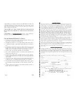
 Hood Pin Switch Control Harness

The hood pin switch MUST be installed with the AutoCommand®.  It
prevents operation of the AutoCommand® when the hood is open.  Connect
the VIOLET wire to the hood pin switch
using the red connector.

Note:

If you already have a hood
pin switch which is being
used by a car alarm sys-
tem, you may share the
wiring -- but be sure
to diode isolate each
wire going to the
hood pin switch
with the bands
of diodes
pointing to-
wards the
pin switch
as fol-
lows:

10. Orange Wire

Brake Shut-off

Control Harness

The ORANGE 18 gauge wire will disable the AutoCommand®  when the brake
pedal is pressed down.  This is an added anti-theft safety feature.  This connec-
tion  is usually  made under or behind the brake pedal linkage at the switch.
Connect the ORANGE to the wire that re12 volt only when the brake
pedal is pressed down.  Any +12 volt input on this wire will shut off the Auto-
Command®.  In some cars, the ignition must be on to see the power at the brake
wire.  This wire must be hooked up.  This is a critical safety feature.  This hook-
up is also required for other options discussed later.

20022

Page 13

 20.  Trouble Shooting with the Self Diagnostics

The AutoCommand® contains a built in diagnostic routine that will indicate
why the unit turned off the car the last time that the unit was used.  To activate
the diagnostic mode, simply turn the On/Off control switch to the “OFF”
position.  In a few seconds, the red LED on the module will flash 1 to 6 times
to identify the problem.  See the chart below for an explanation of the flashes:

1 flash

10/15 minute time out -- unit should be fine.

2 flashes

Brake or Hood activated

3  flashes

No Tach or Stalled.  Check tach learning.  Or confirm that the
alternator is being powered up by one of the ignition wires.

4  flashes

Received another remote input signal.

5 flashes

Transmission was shifted into gear.

6 flashes

Low battery voltage, or  may be missing an ignition wire
which powers up the alternator

8 flashes

Over-current. A transistor output is being over driven.

12  flashes

The control switch was turned off.

In order to get an accurate diagnostic, allow the unit to go through its complete
starting cycle(s).  The unit may only try to start once or it may try 3 times.  In
order to get an accurate reading, please wait 45 seconds after its last attempt to
start.


21.   Special Programming Options

The AutoCommand

®

 unit has 8 special options and features.  You will not

need to use these special options in most situations.  The factory settings will
operate most vehicles.  You must turn the On/Off control switch to the “OFF”
position to program any features.
  Note that when turning off this control
switch, the red LED will flash a few times, giving the diagnostic code described
in Section 20.  Wait a few seconds for it to finish before programming your new

Options.

#

Factory Setting (2 flashes)              Option (1 flash)

1

“No-Tach”

Tach Mode

2

10 min. run time

15 min. run time

3

Normal Crank

Extended Crank

4

Normal Crank

Super Crank

5

Normal Voltage Metering

Ignore Voltage Metering

6

Gasoline vehicles

Diesel vehicles

7

“Enable” feature

No “Enable”

8

Normal Trigger

Double Pulse Trigger

Summary of Contents for AutoCommand 20022

Page 1: ...Control Car Starter Model 20022 Installation Manual For use on automatic vehicles only For gasoline or diesel vehicles AutoCommand V 8 3 pcbv7 3 8 1 7955 Cameron Brown Court Springfield Virginia 22153 USA www designtech intl com ...

Page 2: ...disclaims all other warranties INCLUD ING WITHOUT LIMITATION THE WARRANTIES OF MERCHANT ABILITY AND FIT NESS FOR A PARTICULAR PURPOSE NO PERSON FIRM OR CORPORATION IS AU THORIZED TO ASSUME FOR DESIGNTECH INTERNATIONAL INC ANY OTHER LI ABILITY IN CONNECTION WITH THE SALE AND USE OF THE PRODUCT DesignTech International Inc and agents and distributors will bear no liability whatsoever for incidental ...

Page 3: ...ing the On Off control switch to the OFF position down every time the car is serviced Show the user how the control switch must be turned off and on again after pulling out the key before leaving the car Give the user a copy of the tan colored page USER TIPS AND NOTES so that they can familiarize themselves with the product USER INFORMATION The brown USER TIPS NOTES sheet gives you further detail ...

Page 4: ...lack wire Make several measurements to verify that you have a consistent resistance You also need to change your test leads around You will find that you get two different readings So far we have found that the higher of the two readings is the correct resistance 5 When you have correctly identified the correct resistance obtain a resistance of the same value 6 Locate the Black Bulb Test wire on t...

Page 5: ...wire must only go to the VATS relay If you need IGN2 in the car simply supply power to the IGN2 wire of the vehicle by jumping power from the BLUE IGN1 wire Thus BLUE will be powering up 2 wires behind the key and in some cases 3 wires 2 Diesel Vehicles You must hook the RED BLACK wire up to the diesel glow plug light wire or to the positive side of the vlow plugs itself as described in STEP 18 Th...

Page 6: ...he key switch Lock Off RUN ACC START ACC 20022 Page 15 C You can choose the next option by pushing the left button again to index to the next option When you get to the next option you want to change simply repeat Step B above After six seconds the AutoCommand automatically exits the programming mode Three LED flashes D Turn the Control Switch back ON and confirm that the LED flashes once as the s...

Page 7: ...times 3 will add 50 more crank time to No Tach starting 4 adds 100 more crank time This is necessary on many deisel and hard to start vehicles Options 3 and 4 can be added together for even more cranking time 5 is used in the No Tach starting method for some diesel vehicles 6 option must be activated when installing on a diesel vehicle 7 cancels the Enable mode safety feature The Enable mode requi...

Page 8: ... the red LED on the module will flash 1 to 6 times to identify the problem See the chart below for an explanation of the flashes 1 flash 10 15 minute time out unit should be fine 2 flashes Brake or Hood activated 3 flashes No Tach or Stalled Check tach learning Or confirm that the alternator is being powered up by one of the ignition wires 4 flashes Received another remote input signal 5 flashes T...

Page 9: ...s the car by reading the engine speed tach information from a wire under the hood If you choose tachometer sens ing connect the GREEN 18 awg wire to the car s tach wire under the hood After you have connected the GREEN wire you need to teach the AutoCom mand the vehicle s tach rate Proceed to step 12A Note You must have already initialized the vehicle Page 12 20022 16 Brown Wire Acc Pulse Control ...

Page 10: ...t wire can also be triggered by our optional Smart Car Pager accessory which can be controlled from any telephone anywhere in the world This option requires the pager module an activation fee of 25 and a monthly service fee of 3 00 mo 20022 Page 11 OPTIONAL STEPS Many of the optional steps require a relay to be hooked up The most common relay used for this type of application is the Bosch type aut...

Reviews: