Total Exhaust Hood
Pg.7
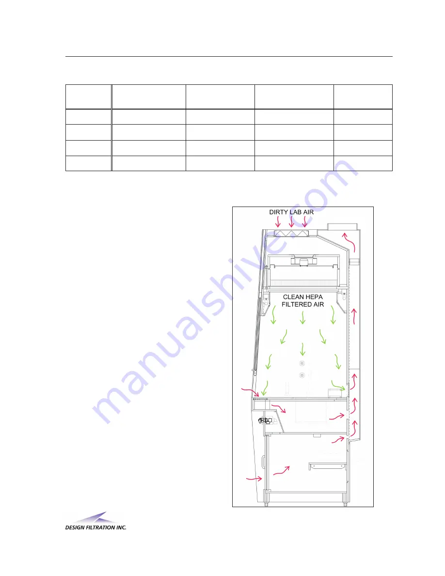
Figure 15.1
14. Airflow Chart Specifications
Model #
Supply (CFM)
(60-70 FPM)
Exhaust (CFM)
Hand Intake (CFM)
(100-110 FPM)
Base Vent
(CFM)
TXH-4
535
846
271
40
TXH-5
673
1054
341
40
TXH-6
811
1262
411
40
TXH-8
1088
1679
551
40
Calculations are based on an average of: 105 FPM for Hand Intake, and 65 FPM for down flow
velocity m easured at 6” below diffuser screen.
15. Airflow Direction
W hen the Total Exhaust Hood is
operating, the fans draw lab air into the
hood from the top through the pre-filter
and the HEPA/ULPA filter, and then
pushes the cleaned air down to the work
surface. Figure15.1 shows the direction
of airflow in the hood.


