background image

47

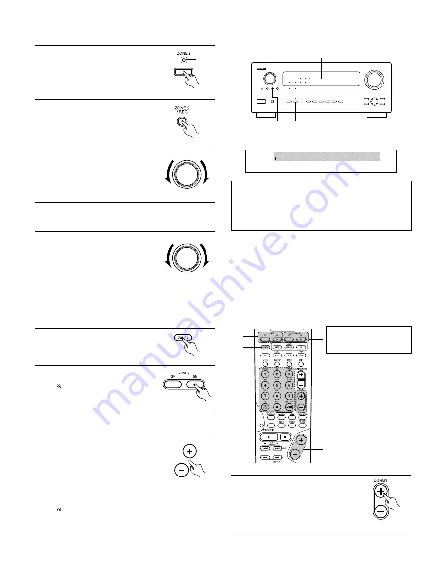
[2] Outputting a program source to an amplifier, etc., in a different room (ZONE2 mode)

1

Press the ZONE2 button.

3

With “ZONE2 SOURCE” displayed, turn
the FUNCTION knob and select the
source you wish to output.
• The indicator of the selected source

light.

FUNCTION

4

Start playing the source to be output.
• For operating instructions, refer to the manuals of the

respective components.

5

To cancel, turn the function knob and
select “SOURCE”.

FUNCTION

3

3,5

2

1

VCR      -1    -2          V.AUX

    /    TAPE   

PHONO  CD   TUNER  

    DVD   /     VDP   TV   /   DBS

2

MULTI

ZONE2    SOURCE

Display

NOTES:

• The signals of the source selected in the ZONE2 mode are also

output from the VCR-1, VCR-2 and CDR/TAPE recording output
jacks.

• Digital signals are not output from the ZONE2 audio output

jacks.

(Main unit)

(Main unit)

(Main unit)

2

Press the ZONE2/REC button.
The display switches as follows each
time the button is pressed.

(Main unit)

Light

3

2
1

4

5

2

Press the ZONE2 “ON” button.

To cancel the ZONE2 mode.
Press the ZONE2 “OFF” button.

(Remote control unit)

3

Press the input source button
• The ZONE2 source switches directly.

4

The output level of the ZONE 2 OUT
terminals can be controlled using the
and - buttons on the remote
control unit.
The output level of ZONE 2 OUT can be
controlled only if ZONE2 vol. level is set
“Variable” at Zone2 Control in System
Setup Menu. (See page 26)

(Remote control unit)

DEFAULT SETTING (ZONE2 VOLUME LEVEL) :
- - - dB (MINIMUM)

5

When the ZONE2 SOURCE function is
set to TUNER, the preset channel can
be selected using the C and
- buttons on the remote control unit.

(Remote control unit)

The main zone output can be
turned on and off with the
“MAIN ON/OFF” button.

[3] Remote control unit operations during multi-source playback (selecting the input source)

1

Select “ZONE2” using the ZONE 2
button.

(Remote control unit)

This operation is possible when ZONE2 mode is selected.
This operation is not possible in the REC OUT mode.

Summary of Contents for AVR-2803

Page 1: ...appreciate your purchase of the AVR 2803 983 2 To be sure you take maximum advantage of all the features the AVR 2803 983 has to offer read these instructions carefully and use the set properly Be sure to keep this manual for future reference should any questions or problems arise SERIAL NO PLEASE RECORD UNIT SERIAL NUMBER ATTACHED TO THE REAR OF THE CABINET FOR FUTURE REFERENCE ...

Page 2: ...ements of the Canadian Interference Causing Equipment Regulations Cet appareil numérique de la classe B respecte toutes les exigences du Règlement sur le matériel brouilleur du Canada WARNING TO PREVENT FIRE OR SHOCK HAZARD DO NOT EXPOSE THIS APPLIANCE TO RAIN OR MOISTURE 2 NOTE ON USE OBSERVATIONS RELATIVES A L UTILISATION Avoid high temperatures Allow for sufficient heat dispersion when installe...

Page 3: ...e ANSI NFPA 70 provides information with regard to proper grounding of the mast and supporting structure grounding of the lead in wire to an antenna discharge unit size of grounding conductors location of antenna discharge unit connection to grounding electrodes and requirements for the grounding electrode See Figure A 16 Lightning For added protection for this product during a lightning storm or ...

Page 4: ...N INSTALLATION Pay attention to the following before using this unit Moving the set To prevent short circuits or damaged wires in the connection cords always unplug the power cord and disconnect the connection cords between all other audio components when moving the set Before turning the power switch on Check once again that all connections are proper and that there are not problems with the conn...

Page 5: ... default digital audio delivery system for DVD and North American DTV 6 Dolby Pro Logic II decoder Dolby Pro Logic II is a new format for playing multi channel audio signals that offers improvements over conventional Dolby Pro Logic It can be used to decode not only sources recorded in Dolby Surround but also regular stereo sources into five channels front left right center and surround left right...

Page 6: ...you wish to connect external power amplifier s to increase the power of the front center and surround sound channels or for connection to powered loudspeakers To use Surround back with one speaker connect the speaker to SURR BACK L CH AC OUTLETS SWITCHED total capacity 120 W 1 A The power to these outlets is turned on and off in conjunction with the POWER operation switch on the main unit and when...

Page 7: ...og audio output jacks ANALOG AUDIO OUTPUT to the DVD IN jacks using pin plug cords A VDP can be connected to the VDP jacks in the same way It is also possible to connect a video disc player DVD player video camcorder Video Game etc to the V AUX jacks AUDIO VIDEO Monitor TV MONITOR OUT Connect the TV s video input jack VIDEO INPUT to the MONITOR OUT jack using a 75 Ω ohms video coaxial pin plug cor...

Page 8: ...VDP DVD Connect the DVD player s S Video output jack to the S VIDEO DVD IN jack using a S Video connection cord A VDP can be connected to the VDP jacks in the same way It is also possible to connect a video disc player DVD player video camcorder game machine etc to the V AUX jacks Connecting a monitor TV MONITOR OUT Connect the TV s S video input S VIDEO INPUT to the MONITOR OUT jack using a S jac...

Page 9: ...nals are not output from the color difference component video output jacks MONITOR OUT DVD player Connecting a DVD player DVD IN jacks Connect the DVD player s color difference component video output jacks COMPONENT VIDEO OUTPUT to the COMPONENT VIDEO 1 IN jack using 75 Ω ohms coaxial video pin plug cords In the same way another video source with component video outputs such as a TV DBS tuner etc ...

Page 10: ... antenna cable plug can be connected directly Connection of AM antennas 1 Push the lever 2 Insert the conductor 3 Return the lever Note to CATV system installer This reminder is provided to call the CATV system installer s attention to Article 820 40 of the NEC which provides guidelines for proper grounding and in particular specifies that the cable ground shall be connected to the grounding syste...

Page 11: ... For instructions on playback using the external input EXT IN jacks see page 44 Connecting the ZONE 2 jacks If another pre main integrated amplifier or power amplifier is connected the ZONE 2 jacks can be used to play a different program source in ZONE 2 the same time See page 48 ZONE 2 For instructions on operations using the ZONE 2 jacks see page 47 48 RC 616 INFRARED RETRANSMITTER Integrated pr...

Page 12: ...ad to damage The protector circuit may be activated if the set is played for long periods of time at high volumes when speakers with an impedance lower than the specified impedance are connected Connection the speaker terminals 1 Loosen by turning counterclockwise 2 Insert the cord 3 Tighten by turning clockwise Connecting banana plugs banana plug Turn clockwise to tighten then insert the banana p...

Page 13: ... with the wiring of the speaker cables or input cables and wait for the unit to cool down if it is very hot Improve the ventilation condition around the unit and switch the power back on If the protection circuit is activated again even though there are no problems with the wiring or the ventilation around the unit switch off the power and contact a DENON service center Protector circuit The prote...

Page 14: ...button 41 63 y ZONE 2 button indicator 47 63 u MODE button 42 44 53 i ANALOG button 42 44 o EXT IN button 42 44 0 DIMMER button 46 1 STATUS button 46 2 SURROUND BACK button 53 3 SURROUND MODE button 43 50 52 53 57 4 SURROUND PARAMETER button 51 52 54 57 5 SELECT knob 43 45 50 54 57 59 6 TONE DEFEAT button 45 7 TONE CONTROL button 45 59 8 MASTER VOLUME control 43 9 Master volume indicator VOLUME LE...

Page 15: ...EN DISPLAY button 34 35 46 TEST TONE button 49 SYSTEM SETUP SETUP button 17 30 34 System buttons 32 34 35 38 MODE SELECT button 32 Input source selector buttons 33 35 42 47 53 61 Mode selector buttons 32 34 36 41 47 Remote control signal transmitter 31 ZONE 2 buttons 47 Cursor buttons 16 CH SELECT ENTER button 16 49 50 RETURN button 34 35 SURROUND BACK button 53 INPUT MODE selector buttons 42 44 N...

Page 16: ... input jacks for the different input sources This sets whether or not to display the on screen display that appears on the monitor screen when the controls on the remote control unit or main unit are operated Input source Digital Inputs Front Sp Large Center Sp Surround Sp Sub Woofer Small Small Yes LFE Front L R Center Surround L R Sub Woofer 12 ft 3 6 m 12 ft 3 6 m 10 ft 3 0 m 12 ft 3 6 m Front ...

Page 17: ...read small characters on TVs with small screens or low resolutions The setup menu is not displayed when headphones are being used Speaker system layout Basic system layout The following is an example of the basic layout for a system consisting of eight speaker systems and a television monitor Subwoofer Center speaker system Surround speaker systems Surround back speaker systems Front speaker syste...

Page 18: ...p Subwoofer Surround Sp Surround back Sp Parameters Large Select this when using speakers that have sufficient performance for reproducing bass sound below the frequency set for the Crossover Frequency mode Small Select this when using speakers that do not have sufficient performance for reproducing bass sound below the frequency set for the Crossover Frequency mode When this is set bass sound wit...

Page 19: ...ove frequency response for frequencies near the crossover frequency Subwoofer mode The subwoofer mode setting is only valid when Large is set for the front speakers and YES is set for the subwoofer in the Speaker Configuration settings see page 18 When the LFE MAIN playback mode is selected the low frequency signal range of channels set to Large are produced simultaneously from those channels and ...

Page 20: ...istance between front speakers and listening position L3 Distance between surround speakers and listening position L4 Distance between surround back speakers and listening position L5 Distance between subwoofer and listening position L1 L2 L5 L3 L4 Center FR FL Subwoofer SL Listening position SR SBR SBL 2 3 4 5 Switch to the Delay Time screen Select the desired unit meters or feet Select darken th...

Page 21: ...n highlighted line Example When the distance is set to 12 feet for the center speaker 7 Enter the setting The System Setup Menu reappears The AVR 2803 983 automatically sets the optimum surround delay time for the listening room NOTE If the distance unit is changed after the delay time is set the settings are reset to the factory default values see page 16 17 Setting the Channel Level Use this set...

Page 22: ...adjust so that the volume of the test tones from the various speakers is the same Example When the volume is set to 11 5 dB while the test tone is being produced from the Front Lch speaker Example When the volume is set to 11 5 dB while the Front Lch speaker is selected Flashing Flashing FL C FR SR SBR SBL SL SW SB 1spkr 2spkrs When the surround back speaker setting is set to 1spkr for Speaker Con...

Page 23: ...then activate the individual surround modes and adjust channel levels that will be remembered for each of those modes Then whenever you activate a particular surround sound mode your preferred channel level adjustments for just that mode will be recalled Check the instructions for adjusting channel levels within each surround mode on page 49 You can adjust the channel levels for each of the follow...

Page 24: ...ng The System Setup Menu reappears q Input source selection w Component video terminal selection Setting the Dolby Digital Setup Sets the down mixing method when not using a center speaker or surround speakers OFF The dynamic range is not compressed ON The dynamic range is compressed automatically according to the combination of speakers being used 1 At the System Setup Menu select Dolby Digital S...

Page 25: ...the ENTER button Setting the ZONE2 Control 2 The Zone2 Control screen appears Select Power Amp Assignment and press the ENTER button 3 Select Surround Back to use as the surround back channel Zone2 to use as Zone 2 out When Surround Back is selected When Zone2 is selected 4 Enter the setting At the Zone2 Control screen select Exit and press the ENTER button The System Setup Menu reappears 2 Settin...

Page 26: ...ontrol screen appears Select Zone2 Vol Level and press the ENTER button Setting the Ext In Subwoofer Level Set the method of playback of the analog input signal connected to the Ext In Subwoofer 1 At the System Setup Menu select Ext In Subwoofer Level 2 Switch to the Ext In Subwoofer Level screen 3 4 Enter the setting The System Setup Menu reappears Select the desired setting Select according to t...

Page 27: ...TS or other multi channel format e Multi channel signals of Dolby Digital DTS or other multi channel format 1 At the System Setup Menu select Auto Surround Mode and press the ENTER button 2 Select ON if you want to use the auto surround mode OFF if you do not want to use it 3 Enter the setting The System Setup Menu reappears Setting the On Screen Display OSD Use this to turn the on screen display ...

Page 28: ...m Setup Menu reappears Auto Tuner Presets Use this to automatically search for FM broadcasts and store up to 40 stations at preset channels A1 to 8 B1 to 8 C1 to 8 D1 to 8 and E1 to 8 NOTE If an FM station cannot be preset automatically due to poor reception use the Manual tuning operation to tune in the station then preset it using the manual Preset memory operation 1 At the System Setup Menu sel...

Page 29: ...o that they cannot be changed easily 1 At the System Setup Menu select Setup Lock 2 Switch to the Setup Lock screen 3 Select ON to lock the system setup settings 4 Press the ENTER to finalize the setting and exit the system setup mode When the setup lock function is activated the settings listed below cannot be changed and Setup Locked is displayed when related buttons are operated System setup se...

Page 30: ...o signal input jack E E C C VIDEO MONITOR OUT video signal output jack yellow C C E E S video MONITOR OUT video signal output jack C E C C On screen display signal output C Signal E No signal C On screen signals output E On screen signals not output NOTES The on screen display signals are not output from the color difference component video signal MONITOR OUT jacks For 4 above the on screen displa...

Page 31: ...old one Do not use two different types of batteries Do not short circuit disassemble heat or dispose of batteries in flames Remove the batteries from the remote control unit when you do not plan to use it for an extended period of time If the battery fluid should leak carefully wipe the fluid off the inside of the battery compartment and insert new batteries When replacing the batteries have the n...

Page 32: ...p 1 Play 8 9 Auto search to beginning of track 3 Pause DISC SKIP for CD changers only 6 Rewind 7 Fast forward 2 Stop 1 Forward play 3 Pause 0 Reverse play A B Switch between sides A and B 3 MD recorder MD CD recorder CDR system buttons 6 7 Manual search forward and reverse 2 Stop 1 Play 8 9 Auto search to beginning of track 3 Pause Default setting CDR 4 Tuner system buttons TUNING Tuning up down B...

Page 33: ...ending on the model and year of manufacture this function cannot be used for some models even if the your device is listed on the included list of preset codes Some manufacturers use more than one type of remote control code Refer to the included list of preset codes to change the number and check it out The preset memory can be set for one component only among the following CDR MD DVD VDP and DBS...

Page 34: ... ON SOURCE 6 7 Manual search forward and reverse 2 Stop 1 Play 8 9 Auto search to beginning of track 3 Pause 0 9 10 10 key DISC SKIP Disc skip for DVD changer only DISPLAY Display MENU Menu RETURN Return SETUP Setup ENTER Enter ª 0 1 Cursor up down left and right 2 Video disc player VDP system buttons POWER Power on standby ON SOURCE 6 7 Manual search forward and reverse 2 Stop 1 Play 8 9 Auto sea...

Page 35: ...l Channels POWER Power on standby ON SOURCE MENU Menu ª 0 1 Cursor up down left and right ENTER Enter CHANNEL Switch channels 0 9 10 Channels TV VCR Switch between TV and video player TV VOL Volume up down DISPLAY Switch display RETURN Return NOTES For this CD CDR MD and TAPE components buttons can be operated in the same way as for Denon audio components The television can be operated in the DVD ...

Page 36: ...hat cannot be learned is pressed To cancel press the USE LEARN button 4 Point the remote control units directly at each other and press and hold in the button on the other remote control unit which you want to learn 5 The mode button and the LEARNED TX indicator lights release the button on the other remote control unit The mode button and the LEARNED TX indicator start flashing again 6 To learn o...

Page 37: ...t source turn on the monitor TV s power turn on the source component s power and set the source to the play mode all at a signal button 3 Press the mode buttons of the equipment that is to be registered to System Call 4 Press the buttons whose remote control signals you want to store one by one 5 Repeat steps 3 and 4 to register the desired buttons 6 Press the CALL1 or CALL2 button and register Sy...

Page 38: ...n the TV mode the CD mode s PLAY STOP MANUAL SEARCH AUTO SEARCH PAUSE and DISC SKIP buttons signals are sent in the TV mode 2 Making the punch through setting 1 2 Press the power ON SOURCE button and the OFF button at the same time The LEARNED TX indicator flashes Press the 1 play button TV and DBS CABLE mode buttons and LEARNED TX indicator flash 1 4 1 3 2 1 3 Press the mode button of the equipme...

Page 39: ...ashes 2 Press the mode button of the equipment that is to be reset Mode button and LEARNED TX indicator flash 3 Hold for 4 seconds or longer the mode button of the equipment that is to be reset and the ON SOURCE button The mode button and the LEARNED TX indicator will again flash and the learned remote control signal of the selected equipment will be deleted 4 Press the USE LEARN button ...

Page 40: ...tons and TEARNED TX indicator flash 3 Press the mode button of the equipment TV or DBS CABLE that is to be reset The CD CDR MD TAPE DVD VDP and VCR mode buttons and TEARNED TX indicator will flash 4 Press the mode button of the equipment that is to be reset again During the resetting operation the selected mode button and the LEARNED TX indicator will light they will return to steady state upon co...

Page 41: ... turns on and the display lights The sound is muted for several seconds after which the unit operates normally When pressed again the power turns off the standby mode is set and the display turns off Whenever the ON STANDBY button is in the STANDBY state the apparatus is still connected on AC line voltage Please be sure to unplug the cord when you leave home for say a vacation Remote control unit ...

Page 42: ...nals is detected the signals input to the digital input jacks are identified and decoding and playback are performed automatically in DTS Dolby Digital or PCM 2 channel stereo format If no digital signal is being input the analog input jacks are selected Use this mode to play Dolby Digital signals w PCM exclusive PCM signal playback mode Decoding and playback are only performed when PCM signals ar...

Page 43: ...Input mode when playing DTS sources Noise will be output if DTS compatible CDs or LDs are played in the ANALOG or PCM mode When playing DTS compatible sources be sure to connect the source component to the digital input jacks OPTICAL COAXIAL and set the input mode to DTS Input mode display In the AUTO mode In the DIGITAL PCM mode In the DIGITAL DTS mode In the ANALOG mode One of these lights depen...

Page 44: ...e control unit When the input mode is set to the external input EXT IN the surround mode DIRECT STEREO DOLBY DTS SURROUND 5 7CH STEREO or DSP SIMULATION cannot be set NOTES In play modes other than the external input mode the signals connected to these jacks cannot be played In addition signals cannot be output from channels not connected to the input jacks The external input mode can be set for a...

Page 45: ...n be increased to up to 10 dB in steps of 2 dB To decrease the bass or treble Turn the control clockwise The bass or treble sound can be decreased to up to 10 dB in steps of 2 dB 2 Listening over headphones 1 Plug the headphones plug into the jack Connect the headphones to the PHONES jack The pre out output including the speaker output is automatically turned off when headphones are connected 1 PH...

Page 46: ...display brightness changes in four steps bright medium dim and off by pressing the main unit s DIMMER button repeatedly 1 Main unit Remote control unit Multi source recording playback 1 Playing one source while recording another REC OUT mode 1 Press the ZONE2 REC button 2 With RECOUT SOURCE displayed turn the FUNCTION knob to select the source you wish to record The REC indicator and the indicator...

Page 47: ...button is pressed Main unit Light 3 2 1 4 5 2 Press the ZONE2 ON button To cancel the ZONE2 mode Press the ZONE2 OFF button Remote control unit 3 Press the input source button The ZONE2 source switches directly 4 The output level of the ZONE 2 OUT terminals can be controlled using the VOLUME and buttons on the remote control unit The output level of ZONE 2 OUT can be controlled only if ZONE2 vol l...

Page 48: ...rround Back Speaker Out cannot be used for MAIN ZONE See page 25 When a sold separately room to room remote control unit DENON RC 616 617 or 618 is wired and connected between the MAIN ZONE and ZONE 2 the remote controllable devices in the main zone can be controlled from ZONE 2 using the remote control unit To control playback devices other than the ones above either use that device s remote cont...

Page 49: ... the volume of the test tones is the same for all the speakers After adjusting using the test tones adjust the channel levels either according to the playback sources or to suit your tastes as described below 2 1 3 2 3 After completing the adjustment press the TEST TONE button again 1 Select the speaker whose level you want to adjust Remote control unit 2 Adjust the level of the selected speaker T...

Page 50: ...to 12 dB using the fader function If the channel levels are adjusted separately after adjusting the fader the fader adjustment values are cleared so adjust the fader again Dolby Surround Pro Logic II mode 1 Select the Dolby Surround Pro Logic II mode The Dolby Pro Logic indicator lights 2 Play a program source with the mark For operating instructions refer to the manuals of the respective componen...

Page 51: ...ters are set using the buttons on the main unit stop operating buttons after completing the settings The settings are automatically finalized and the normal display reappears after several seconds When the settings are made using the buttons on the remote control unit press the SURROUND PARAMETER button to finish Surround parameters q Pro Logic II Mode The Cinema mode is for use with stereo televi...

Page 52: ...te control unit This is the screen when operated with the remote control unit 5 Select the various parameters See Surround parameters e on page 59 for a description of the various parameters Main unit Remote control unit NOTE When Default is selected and the 0 cursor button is pressed MODE and TONE are automatically reset to the default values and CINEMA EQ is set to OFF 6 Set the various surround...

Page 53: ...TS indicator lights when playing DTS sources Remote control unit Light Light SELECT 1 3 2 4 5 2 6 3 1 1 2 1 4 3 5 6 Main unit Main unit SIGNAL DETECT The SIGNAL DETECT LED lights when playing 6 1 channel surround sources containing the identification signal Light When the SIGNAL DETECT LED is lit we recommend turning the surround back channel using the SURROUND BACK button on the remote control un...

Page 54: ...rrect DTS playback When DTS encoded music software is played it is recommended that the LFE LEVEL be set to 10 dB for correct DTS playback TONE This adjusts the tone control See Surround parameters e on page 59 SB CH OUT 1 Dolby Digital DTS source OFF Playback is conducted without using the surround back speaker NON MTRX Playback is conducted using the surround back speaker The same signals those ...

Page 55: ...annels is output to the center channel Use this mode to enjoy stereo sound 5 6 MATRIX VIRTUAL Select this to emphasize the sense of expansion for music sources recorded in stereo Signals consisting of the difference component of the input signals the component that provides the sense of expansion processed for delay are output from the surround channel Select this mode to enjoy a virtual sound fie...

Page 56: ...he parameters 4 To end the setting mode press the surround parameter button again Remote control unit Remote control unit Remote control unit Remote control unit NOTES When Default is selected and the 0 courser button is pressed CINEMA EQ and D COMP are automatically turned off ROOM SIZE is set to medium EFFECT LEVEL to 10 DELAY TIME to 30ms and LFE to 0dB The ROOM SIZE expresses the expansion eff...

Page 57: ... 2 1 3 Main unit Main unit To select the surround mode while adjusting the surround parameters or tone control press the surround mode button then operate the selector NOTE When playing PCM digital signals or analog signals in the DOLBY PRO LOGIC II DTS NEO 6 modes and the input signal switches to a digital signal encoded in Dolby Digital the Dolby surround mode switches automatically When the inp...

Page 58: ...round modes 1 Display the surround parameter screen on the monitor The screen for the selected surround mode appears TONE cannot be selected in the Direct mode 2 3 4 1 6 5 2 Select TONE 3 Switch to the Tone Control screen Select Tone Defeat OFF 4 5 Enter the setting The surround menu screen re appears 6 To end the setting mode press the surround parameter button again To select Bass or Treble To s...

Page 59: ...ll because the in phase component is assigned mainly to the center channel C and the reversed phase component to the surround SL SR and SB channels Music This mode is suited mainly for playing music The front channel FL and FR signals bypass the decoder and are played directly so there is no loss of sound quality and the effect of the surround signals output from the center C and surround SL SR an...

Page 60: ...EL DELAY TIME When playing Dolby Digital DTS signals D COMP LFE DIRECT STEREO EXTERNAL INPUT DOLBY PRO LOGIC II DTS NEO 6 DOLBY DIGITAL DTS SURROUND DTS ES MTRX 6 1 5 7CH STEREO ROCK ARENA JAZZ CLUB VIDEO GAME MONO MOVIE MATRIX VIRTUAL E C 0dB E C 0dB C 0dB C 0dB C 0dB C 0dB C Note1 C 0dB C 0dB C 0dB C 0dB C 0dB E E E C OFF Note2 C OFF Note3 C OFF C OFF E E E E E E E E E E E E E E E C Medium C Med...

Page 61: ...ote control unit is set to AMP mode TAPE CDR MD or CD FUNCTION 2 Watching the display press the BAND button to select the desired band AM or FM 3 Press the MODE button to set the manual tuning mode Check that the display s AUTO indicator turns off Main unit Remote control unit Remote control unit Remote control unit 4 Press the TUNING up or down button to tune in the desired station The frequency ...

Page 62: ...ess the MEMORY button again to store the station in the preset memory Remote control unit Remote control unit To preset other channels repeat steps 2 to 5 A total of 40 broadcast stations can be preset 8 stations channels 1 to 8 in each of blocks A to E The preset broadcast stations can be checked on the on screen display 1 Press the ON SCREEN DISPLAY button repeatedly until the Tuner Preset Stati...

Page 63: ...rd disconnected 14 INITIALIZATION OF THE MICROPROCESSOR When the indication of the display is not normal or when the operation of the unit does not shows the reasonable result the initialization of the microprocessor is required by the following procedure 1 Switch off the unit and remove the AC cord from the wall outlet 2 Hold the following FRONT SPEAKER button and ZONE 2 button and plug the AC co...

Page 64: ...of speaker cords Incomplete connection of input output cords Connect securely Connect securely 12 6 13 Positions of instruments reversed during stereo playback Reverse connections of left and right speakers or left and right input output cords Check left and right connections 12 The on screen display is not displayed On screen display is set to off on the system setup menu screen Set on screen dis...

Page 65: ...R SB Multiple surround speakers Movie theater sound field Listening room sound field In this case it is important to achieve the same sense of expansion as in a movie theater with the surround channels To do so in some cases the number of surround speakers is increased to four or eight or speakers with bipolar or dipolar properties are used Other types of audio These signals are designed to recrea...

Page 66: ... Movement of acoustic image from SR to SL Change of positioning and acoustic image with 6 1 channel systems Movement of acoustic image from SR to SB to SL 2 Number of surround back speakers Though the surround back channel only consists of 1 channel of playback signals for 6 1 channel sources DTS ES etc we recommend using two speakers When using speakers with dipolar characteristics in particular ...

Page 67: ...hannel signals from reflecting off the monitor or screen at the front center resulting in interference and making the sense of movement from the front to the back less sharp Speaker setting examples Here we describe a number of speaker settings for different purposes Use these examples as guides to set up your system according to the type of speakers used and the main usage purpose 1 DTS ES compat...

Page 68: ...erence page 1 Please use a commercially available adapter when connecting the Dolby Digital RF output jack of the LD player to the digital input jack Please refer to the instruction manual of the adapter when making connection 2 Some DVD digital outputs have the function of switching the Dolby Digital signal output method between bit stream and convert to PCM When playing in Dolby Digital surround...

Page 69: ... the un decoded DTS signals are output as random hissy noise from the CD or LD player s analog outputs If this noise is played with the amplifier set at a very high volume it may possibly cause damage to the speakers To avoid this be sure to switch the input mode to AUTO or DTS before playing CDs or LDs recorded in DTS Also never switch the input mode to ANALOG or PCM during playback The same hold...

Page 70: ...aims than with conventional 5 1 or 6 1 channel systems In addition the bit stream format is 100 compatible with conventional DTS signals so the effect of the Matrix 6 1 format can be achieved even with 5 1 channel signal sources Of course it is also possible to play DTS ES Matrix 6 1 encoded sources with a DTS 5 1 channel decoder When DTS ES Discrete 6 1 or Matrix 6 1 encoded sources are decoded w...

Page 71: ...wide frequency range of over 40 kHz In addition DTS 96 24 has a resolution of 24 bits resulting in the same frequency band and dynamic range as 96 kHz 24 bit PCM As with conventional DTS Surround DTS 96 24 is compatible with a maximum of 5 1 channels so sources recorded using DTS 96 24 can be played in high sampling frequency multiple channel audio with such normal media as DVD videos and CDs Thus...

Page 72: ...er is for optimizing the timing with which the audio signals are produced from the speakers and subwoofer according to the listening position SBL SBR 10 ft 3 0 m r Surround Back L 0 dB Surround L 0 dB TAPE OPT4 Crossover Frequency Set the frequency Hz below which the bass sound of the various speakers is to be output from the subwoofer 80 Hz Video In Assign This assigns the color difference compon...

Page 73: ...L DELAY TIME When playing Dolby Digital DTS signals D COMP LFE DIRECT STEREO EXTERNAL INPUT DOLBY PRO LOGIC II DTS NEO 6 DOLBY DIGITAL DTS SURROUND DTS ES MTRX 6 1 5 7CH STEREO ROCK ARENA JAZZ CLUB VIDEO GAME MONO MOVIE MATRIX VIRTUAL E C 0dB E C 0dB C 0dB C 0dB C 0dB C 0dB C Note1 C 0dB C 0dB C 0dB C 0dB C 0dB E E E C OFF Note2 C OFF Note3 C OFF C OFF E E E E E E E E E E E E E E E C Medium C Medi...

Page 74: ...CT STEREO DTS SURROUND DOLBY SURROUND DSP SIMULATION C C DTS NEO 6 DOLBY PRO LOGIC II C C C DTS ES MTRX DTS SURROUND E C C C DTS ES MTRX DTS 96 24 E C C C B ES DSCRT6 1 ES MTRX6 1 DTS SURROUND E C C C DTS NEO 6 DOLBY PRO LOGIC II C Surround Mode LINEAR PCM C C DTS NEO 6 DOLBY PRO LOGIC II C D D 5 1 ch DOLBY DIGITAL DTS C C E DOLBY DIGITAL EX DOLBY DIGITAL C Input signals 2 Differences in surround ...

Page 75: ...o 74 dB A weighting with 5 mV input Rated output Maximum output 150 mV 8 V Distortion factor 0 03 1 kHz 3 V 2 Video section Standard video jacks Input output level and impedance 1 Vp p 75 Ω ohms Frequency response 5 Hz 10 MHz 0 3 dB S video jacks Input output level and impedance Y signal 1 Vp p 75 Ω ohms C signal 0 286 Vp p 75 Ω ohms Frequency response 5 Hz 10 MHz 0 3 dB Color component video jack...

Page 76: ...Printed in Japan 511 4012 002 16 11 YUSHIMA 3 CHOME BUNKYOU KU TOKYO 113 0034 JAPAN Telephone 03 3837 5321 ...

Reviews: