background image

Get
ting Star

ted

Connections

Set
up

Remot

e Contr

ol

Multi-Zone

Inf
or

mation

Tr

oubleshooting

ENGLISH

• The  title  name,  artist  name  and  album  name  can  be  checked  by 

pressing 

[STATUS]

 during playback.

• On the AVR-2308, folder and fi le names can be displayed as titles. Any 

characters that cannot be displayed are replaced with “ . (period)”.

• The time for which the on-screen display are displayed can be set 

at menu “Manual Setup” – “Option Setup” – “On-Screen Display” 
– “iPod Information” (

v

page 31).

Viewing Still Pictures or Videos on the 

iPod

Photo and video data on the iPod can be viewed on the monitor. 
Only for iPod equipped with slideshow or video functions. (When 
using an ASD-1R)

1


Press and hold 

[MODE]

 to set the Remote mode.

“Remote iPod” is displayed on the AVR-2308’s display.

2


Watching  the  iPod’s  screen,  use 

[

ui

]

  to  select 

“Photos” or “Video”.

3


Press 

[ENTER]

  until  the  image  you  want  to  view  is 

displayed.

“TV Out” at the iPod’s “Slideshow Settings” or “Video Settings” must 
be set to “On” in order to display the iPod’s photo data or videos on 
the monitor. For details, see the iPod’s operating instructions.

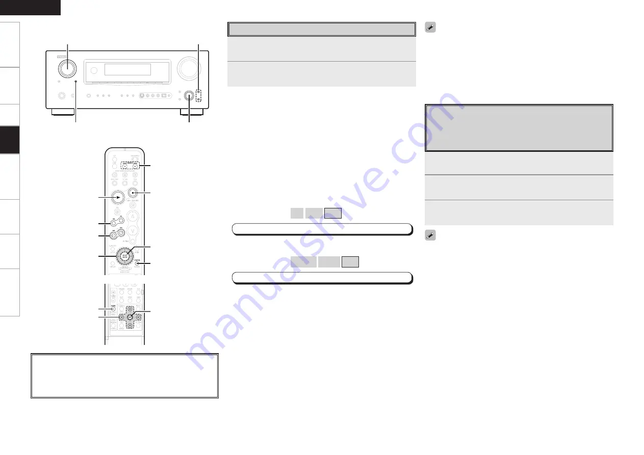
About the button names in these explanations


<


>

  : Buttons on the main unit


[


]


: Buttons on the remote control unit

Button name only:

  Buttons on the main unit and remote control unit

<SOURCE SELECT>

<ZONE2/REC SELECT>

<ENTER>,

op

ui

uiop

[

1

]

[

6

], [

7

]

[

8

], [

9

]

[

2

]

[ENTER],

[CH SELECT]

[C/–]

[STATUS]

uiop

[ENTER]

[MODE]

[Front]

[Rear]

Listening to Music

1


Use 

[

ui

]

 to select the menu, then press 

[ENTER]

 or 

[

p

to select the music fi le to be played.

2


Press 

[ENTER]

 or 

[

p

]

.

Playback starts.

Stopping playback temporarily

During playback, press 

[ENTER]

 or 

[

1

]

.

Press again to resume playback.

Fast-forwarding or fast-reversing

During playback, either press and hold 

[

u

]

 (to fast-reverse) or 

[

i

]

 (to 

fast-forward), or press 

[

6

]

 or 

[

7

]

.

To cue to the beginning of a track

During playback, either press 

[

u

]

 (to cue to the previous track) or 

[

i

]


(to cue to the next track), or press 

[

8

]

 or 

[

9

]

.

To stop

During playback, either press and hold 

[ENTER]

 or press 

[

2

]

.

Playing repeatedly

Press 

[CHANNEL –]

.

[Selectable items] 

All


One


OFF

MENU


”Input Setup” 

– 

”iPod” 

– 

“Repeat”

 (

v

page 35)

Shuffl ing playback

Press 

[C]

.

[Selectable items] 

Albums


Songs


OFF

MENU


”Input Setup” 

– 

”iPod” 

– 

“Shuffl e”

 (

v

page 35)

To switch between the Browse and Remote modes

Either press and hold 

[MODE].

Pla
ybac

k

Summary of Contents for AVR-2308

Page 1: ...AV SURROUND RECEIVER AVR 2308 Owner s Manual Bedienungsanleitung Manuel de l Utilisateur Italiano Español Nederlands Svenska Book 2 v English Deutsch Français PRESET CODE Book 1 ...

Page 2: ...tspricht EN60065 EN55013 EN55020 EN61000 3 2 und EN61000 3 3 Entspricht den Verordnungen der Direktive 2006 95 EC 89 336 EEC und 93 68 EEC DECLARATION DE CONFORMITE Nous déclarons sous notre seule responsabilité que l appareil auquel se réfère cette déclaration est conforme aux standards suivants EN60065 EN55013 EN55020 EN61000 3 2 et EN61000 3 3 D après les dispositions de la Directive 2006 95 EC...

Page 3: ...alor cuando está instalado en la consola Vermijd hoge temperaturen Zorg er bij installatie in een audiorack voor dat de door het toestel geproduceerde warmte goed kan worden afgevoerd Undvik höga temperaturer Se till att det finns möjlighet till god värmeavledning vid montering i ett rack Handle the power cord carefully Hold the plug when unplugging the cord Gehen Sie vorsichtig mit dem Netzkabel ...

Page 4: ...mento dell unità osservare le normative o le leggi locali in vigore Non gettare le batterie né incenerirle ma smaltirle conformemente alla normativa locale sui rifiuti chimici Questo prodotto e gli accessori inclusi nell imballaggio sono applicabili alla direttiva RAEE ad eccezione delle batterie ACERCA DEL RECICLAJE Los materiales de embalaje de este producto son reciclables y se pueden volver a ...

Page 5: ...kip 33 Preset Name 33 Input Mode 34 Rename 34 Assign 34 35 iPod 35 Other 35 36 Input Setup Contents Speaker Setup 25 a Speaker Configuration 25 s Subwoofer Setup 25 d Distance 25 26 f Channel Level 26 g Crossover Frequency 26 HDMI Setup 27 a HDMI Audio Setup 27 s HDMI Video Setup 27 Audio Setup 28 a EXT IN Subwoofer Level 28 s 2ch Direct Stereo 28 d Dolby Digital Setup 28 f Auto Surround Mode 28 g...

Page 6: ...DS Radio Data System 45 RDS Search 46 PTY Search 46 TP Search 46 RT Radio Text 47 iPod Playback 47 Basic Operation 47 Listening to Music 48 Viewing Still Pictures or Videos on the iPod 48 Playback Other Operations 49 Recording on an External Device REC OUT mode 49 Convenient Functions 49 Channel Level 49 Fader Function 49 Quick Select Function 50 Personal Memory Plus Function 50 Last Function Memo...

Page 7: ...te Control Unit Point the remote control unit at the remote sensor when operating it NOTE The set may function improperly or the remote control unit may not operate if the remote control sensor is exposed to direct sunlight strong artificial light from an inverter type fluorescent lamp or infrared light Before turning the power switch on Check once again that all connections are correct and that t...

Page 8: ...n the REC OUT mode is selected Q1 NIGHT indicator This lights when the night mode is selected Q2 RESTORER indicator This lights when the RESTORER mode is selected Q3 HDMI indicator This lights when playing using HDMI connections Q4 Decoder indicators These light when the respective decoders are operating Q5 Tuner reception mode indicators These light according to the reception conditions when the ...

Page 9: ...CONTROL jack 14 t Speaker terminals SPEAKERS 9 y SIGNAL GND terminal 13 u AC OUTLET 19 i Power cord 19 o Digital audio connectors OPTICAL COAXIAL 12 15 Q0 COMPONENT VIDEO connectors 12 Q1 HDMI connectors 11 Q2 VIDEO S VIDEO connectors 12 Q3 Analog audio connectors AUDIO 12 Q4 FM AM antenna terminals TUNER ANTENNA 17 Q5 ZONE2 connectors 18 Q6 EXT IN connectors 16 Q7 PRE OUT connectors 9 Rear Panel ...

Page 10: ...control signal transmitter 3 Q3 Master volume control buttons 43 Q4 MUTING button 43 Q5 NIGHT button 41 Q6 STATUS button 48 Q7 Channel select CH SEL ENTER button 19 49 q e w r t y i Q1 Q0 u o q ZONE2 power buttons 58 w Source select buttons 43 e Tuner system buttons 44 45 r Test tone button TEST 26 t Main zone power buttons MAIN 58 y Surround mode buttons 36 37 u Amp menu button A MENU 19 i Input ...

Page 11: ...tput Input Input Output Output Input Input Output Cables Used for Connections Select the cables according to the equipment being connected Preparations Connections NOTE Do not plug in the power cord until all connections have been completed When making connections also refer to the operating instructions of the other components Be sure to connect the left and right channels properly left with left...

Page 12: ... cannot be converted into analog signals 1080p component input video signals cannot be output to anything other than component video connectors 480p 576p 1080i and 720p component video input signals cannot be converted into S Video or Video format When a non standard video signal from a game machine or some other source is input the video conversion function might not operate When not using this f...

Page 13: ...creen surface as possible The table below shows a typical speaker configuration for the AVR 2308 Surround back speakers FRONT CENTER SURROUND SURROUND BACK SUBWOOFER L R L R L R 1 only 7 1 channels FRONT A B S S S S S S S S 7 1 channels S S S S S S S S 6 1 channels S S S S S S S 5 1 channels S S S S S S 3 1 channels S S S S 2 1 channels S S S 2 channels S S Speaker Connections Example 5 1 channels...

Page 14: ...s The protection circuit may be activated if the core wires touch the rear panel or if the and sides touch each other v Protection circuit Never touch the speaker terminals while the power supply is connected Doing so could result in electric shock Protection circuit If speakers with an impedance lower than specified for example 4 Ω ohms speakers are used for an extended period of time with the vo...

Page 15: ...tically compatible with the DVI format When connecting to a monitor etc equipped with a DVI D connector connection is possible using an HDMI DVI converter cable but depending on the combination of components in some cases the video signals will not be output When connecting using an HDMI DVI converter adapter the video signals may not be output properly due to poor connections with the connected c...

Page 16: ...Connecting the Playback Components DVD Player Connect the cables to be used With HDMI connections the video and audio signals can be transferred with a single cable DVD player NOTE The component video connectors may be indicated differently on your monitor For details see the monitor s operating instructions No audio signals are output from the HDMI monitor output connector To play the sound by mo...

Page 17: ...h no record player connected With some record players noise may be generated when the ground wire is connected If so disconnect the ground wire 6 0 065 R L Turntable MM cartridge NOTE The AVR 2308 s SIGNAL GND terminal is meant to reduce noise when a record player is connected This is not a safety ground terminal R L R L 6 0 6 0 0 9 065 3 065 CD Player Connect the cables to be used CD player When ...

Page 18: ...t Setup Assign Digital In vpage 35 iPod R L R L 4 3 iPod With the default settings the iPod can be used connected to the VCR iPod connector To assign the iPod to a connector other than VCR iPod make the settings at menu Input Setup input source to which iPod dock assigned Assign iPod dock vpage 35 Use a DENON Control Dock for iPod ASD 1R sold separately to connect the iPod to the AVR 2308 For inst...

Page 19: ...back device s cable must be of the same type as the cable used to connect the AVR 2308 s DVR OUT connector Example TV IN S Video cable DVR OUT S Video cable TV IN Video cable DVR OUT Video cable When using a component video cable for the video connection make the settings at menu Input Setup Assign Component In vpage 35 or or R L R L R L R L 4 7 0 3 3 065 6 0 7 0 065 6 0 7 0 065 Video Cassette Rec...

Page 20: ...ht R channels and the inputs and outputs and be sure to interconnect correctly Connections to Other Devices Component with Multi channel Output connectors R L R L R L R L R L R L 46 800 3 5 3 463306 3 463306 3 30 5 3 6 0 DVD player Super Audio CD player External decoder To play the analog input signals input to the EXT IN connectors press the EXT IN button on the main unit or INPUT button on the r...

Page 21: ...he vinyl tie and take out the connection line Connect to the AM antenna terminals Bend in the reverse direction a With the antenna on top of any stable surface Mount b With the antenna attached to a wall Installation hole Mount on wall etc Connection of AM antennas 1 Push the lever 2 Insert the conductor 3 Return the lever NOTE Do not connect two FM antennas simultaneously Even if an external AM a...

Page 22: ...CI sold separately two way communication with an RF Remote Controller is possible The AVR 2308 s status information as well as iPod can be browsed watching the RF Remote Controller s display For details refer to the operating instructions of the respective devices When used in combination with an RF Remote Controller or RF Remote Receiver make the settings at menu Manual Setup Option Setup 2Way Re...

Page 23: ... unit Buttons on the remote control unit Button name only Buttons on the main unit and remote control unit ENTER op RETURN ui MENU 1Press MENU The menu is displayed b To operate from the remote control unit be sure to set the MODE SELECTOR 1 to AUDIO 2Press ui to select the item you want to set then press ENTER 3Press ui again to select the item you want to set then press ENTER 4To change the sett...

Page 24: ... Speaker Detection at ear height at Front Sp A Amp Assign Start Cancel Please place microphone main listening position 3 1 Assign Digital In OPT1 iPod Dock None 2 1 3 Distance Set The Distance To Meters Feet Each Speakers Do You Prefer In Meters In Feet Assign Digital OPT1 EQ Screen title Menu number Submenu title Press o to execute Press op to change the setting Current setting Currently selected...

Page 25: ...Volume Limit Power On Level Mute Level Source Delete On Screen Display Screensaver Text Master Volume Tuner Information iPod Information Display Mode Quick Select Name Trigger Out Remote ID Setup 2Way Remote Display Setup Lock Parameter vpage 38 41 n Surround Parameter MODE CINEMA EQ D COMP LFE CENTER IMAGE PANORAMA DIMENSION CENTER WIDTH DELAYTIME EFFECT LEVEL ROOM SIZE AFDM SB CH OUT SW ATT Subw...

Page 26: ...ction make the following settings before starting the auto setup procedure Volume Center Crossover frequency Maximum Low pass filter Off Standby mode Off NOTE Do not disconnect the setup microphone until the auto setup procedure is completed When using headphones unplug the headphones before starting the auto setup procedure Auto Setup To set the listening environment manually to suit your tastes ...

Page 27: ...t Menu The settings are performed automatically NOTE Do not turn the power off while the settings are being stored in the memory Step 2 Measurements The listening environment with respect to the listening position Speaker size check Crossover Frequency check and Room EQ correction is measured automatically at positions 2 to 6 Once a measurement is made move the setup microphone to the next positio...

Page 28: ...ot all speakers could be detected Connect the included setup microphone to the SETUP MIC jack on the main unit Check the speaker connections too high or Retry Cancel Ambient noise is Level is too low Auto Setup Caution Too much noise in the room for accurate measurements to be made Speaker or subwoofer sound is too low for accurate measurements to be made Either turn off any device generating nois...

Page 29: ... connect it to the left channel SBL Large Select this when using large speakers with ample low frequency reproduction capabilities Small Select this when using small speakers without ample low frequency reproduction capabilities None Select this when no speaker is connected Yes Select this when a subwoofer is connected No Select this when no subwoofer is connected 2spkrs 1spkr Select the number of...

Page 30: ...range 12dB 0dB 12dB Distance measurement Select the speaker you want to set then set the distance Set the value closest to the measured distance Variable range 0 00m 18 00m Display when Meters is set 0 0ft 60 0ft Display when Feet is set NOTE Set the distance between the listening position and the various speakers to no more than 6 00 meters 20 0 ft Default Resets the settings to the default value...

Page 31: ...d automatically set output resolution 480p 576p Output at 480p 576p resolution 1080i Output at 1080i resolution 720p Output at 720p resolution 1080p Output at 1080p resolution Progressive Mode Select optimum progressive mode for video material Selectable items Auto Automatically detect video material type Video1 Select mode suitable for video playback Video2 Select mode suitable for video and 30 f...

Page 32: ...m 18 00m Distance FR Set distance from listening position to front right speaker Variable range 0 00m 18 00m d Dolby Digital Setup Set dynamic range for downmix playback of Dolby Digital sources Set this to ON if the sound from the front speakers seems distorted When not using the center speaker or surround speakers the playback sound is down mixed and output from the front speakers Selectable ite...

Page 33: ...tem F Menu screen F 2 Manual Setup 2 HDMI Setup 1 Speaker Setup 4 Zone2 Setup 5 Option Setup 3 Audio Setup a Lch Level Adjust the left channel output level 2 4 Zone2 Setup Level Lch 0dB Rch 0dB Vol Limit OFF Power On Lev Last Mute Lev Full Selectable items Last Use the memorized setting from the last session Always use the muting on condition when power is turned on 70dB 18dB Set the volume level ...

Page 34: ...n 2 5 Option Setup s Volume Control Set the main zone volume setting Volume Limit Make a setting for maximum volume Selectable items OFF Do not set a maximum volume 20dB Set the maximum volume to 20 dB 10dB Set the maximum volume to 10 dB 0dB Set the maximum volume to 0 dB Power On Level This sets the volume set when the main zone s power is turned on Selectable items Last Use the memorized settin...

Page 35: ...e on screen display when there is no video signal Use this mode if the on screen display does not appear in the Mode 1 as may happen according to the TV being used iPod Information This sets the time the on screen display is displayed when an operation is performed Selectable items Always Show display continuously 30sec Show display for 30 seconds after operation 10sec Show display for 10 seconds ...

Page 36: ...ness Dark Very low display brightness OFF Display is off unless controls are operated NOTE When using the AVR 2308 with only the included remote control unit RC 1081 there is no need to make settings When using a separately sold remote control unit RC 7000CI etc this function can be used Match the ID setting of the remote control unit and the receiver A0 Setup Lock Protect settings from inadverten...

Page 37: ...u screen F 1 Assign 2 Input Mode 3 Rename 4 Other 3 Input Setup CD b The menu settings below can be made for these input sources when iPod dock is set to Assign 1 Assign 2 Input Mode 3 Rename 4 Other 5 iPod 3 Input Setup VCR Repeat OFF Shuffle OFF 3 5 iPod Auto Preset Use the auto preset function to program radio stations Input source TUNER Selectable items Start Start the auto preset process If a...

Page 38: ...etect type of digital input signal and decode and play automatically PCM Decode and play only PCM input signals DTS Decode and play only DTS input signals This can be selected for input sources for which the menu Assign setting is set to HDMI or Digital In vpage 35 Only set PCM and DTS when playing the respective signals With HDMI the video and audio signals are transferred simultaneously When HDM...

Page 39: ...V AUX Selectable items Assign Assign iPod input None Do not assign iPod input With the default settings the Control Dock for iPod can be used connected to the VCR iPod connector Even if iPod dock is set to Assign if the AVR 2308 is not connected to a Control dock for iPod the input source can be used as the normal input source iPod Make settings for iPod playback Input source CD AUX DVD HDP TV CBL...

Page 40: ...tal input level can be set separately Video Convert Automatically convert video input signal to monitor output format Input source DVD HDP TV CBL VCR DVR V AUX Selectable items ON Enable conversion OFF Disable conversion Select the Cinema Music Game and Pro Logic modes at menu Parameter Surround Parameter MODE vpage 38 Input signal Display Dolby Digital Source DOLBY DIGITAL other than 2ch DOLBY DI...

Page 41: ...OVIE mode the sound will be off balance with a single channel left or right so input to both channels Input signal Display Analog signal PCM 2ch Dolby Digital source DTS source Other 2 channel digital signals DIRECT PCM multi ch MULTI CH DIRECT M DIRECT PLgx CINEMA M DIRECT PLgx MUSIC M DIRECT 7 1 For details see page 65 Direct Playback Selectable items DIRECT In this mode the signals bypass the t...

Page 42: ...range difference between loud and soft sounds Selectable items OFF Turn dynamic range compression off LOW Low setting MID Middle setting HIGH High setting When playing DTS sources this is only displayed for compatible software LFE Adjust the low frequency effects level LFE Variable range 10dB 0dB CENTER IMAGE Assign center channel signal to front left and right channels for wider sound Variable ra...

Page 43: ...nnel signals undergo digital matrix processing and are output from the surround back channels PLIIx CINEMA z1 Decoded in Dolby Pro Logic IIx Cinema mode surround back signal played PLIIx MUSIC z2 Decoded in Dolby Pro Logic IIx Music mode surround back signal played ES MTRX z3 DTS signal played with digital matrix processing ES DSCRT z4 Signal included in DTS ES Discrete 6 1 channel sources played ...

Page 44: ...xcept front speakers to match room acoustics Audyssey Flat Optimize frequency response of all speakers to flat response Manual Apply frequency response set with Manual EQ vpage 29 OFF Turn equalizer off f RESTORER This function restores compressed audio signals to how they were before compression and corrects the sense of volume of the bass to obtain richer playback sound About the RESTORER functi...

Page 45: ...ked Select Source Name Surround Mode Input Mode Rec Select Video Select Source Level Room EQ Night Mode RESTORER etc s ZONE2 Shows information about settings for multi zone Items to be checked Power Select Source Volume Level Name Record Surround Mode STEREO Select Source 5 1 Status PHONO Input Mode ANALOG 1 4 Audio Input Signal Shows information about audio input signals F Menu screen F 2 Audio I...

Page 46: ...enu screen F 2 Audio Input Signal 3 HDMI Information 4 Auto Surround Mode 5 Quick Select 6 Preset Station 1 Status 5 Information For instructions on storing settings at Quick Select 1 to 3 see page 50 Items to be checked Name Input Source Input Mode Volume Level Analog PCM 2CH Multi ch Digital 2CH Digital 5 1CH Preset Station Shows information about preset stations F Menu screen F 2 Audio Input Si...

Page 47: ...to some of the circuitry even when the power is in the standby mode When leaving home for long periods of time or when traveling either press POWER to turn off the power or unplug the power cord from the power outlet Turning the Power On Either turn MASTER VOLUME or press MASTER VOLUME Operations During Playback Adjusting the Master Volume Press MUTING To cancel press MUTING again Muting can also ...

Page 48: ...s continuously The time for which the on screen display are displayed can be set at Manual Setup Option Setup On Screen Display vpage 31 Basic Operation PlayingVideo and Audio Equipment 1Prepare the equipment qLoad the DVD CD or other software in the player vSee the operating instructions of the respective devices wTo play a video device switch the monitor input vSee the monitor s operating instru...

Page 49: ...M Other Music WEATHER Weather FINANCE Finance CHILDREN Children s programmes SOCIAL Social Affairs RELIGION Religion PHONE IN Phone In TRAVEL Travel LEISURE Leisure JAZZ Jazz Music COUNTRY Country Music NATION M National Music OLDIES Oldies Music FOLK M Folk Music DOCUMENT Documentary RDS Radio Data System RDS works only on the FM band is a broadcasting service which allows a station to send addit...

Page 50: ...ction to find RDS stations broadcasting traffic programs TP stations 1Either turn SOURCE SELECT or press TUNER to select TUNER 2Set MODE SELECTOR 1 to AUDIO vpage 51 Remote Control Unit Operations 3Press RDS until RDS SEARCH appears on the display 4Press PRESET CHANNEL The search for RDS stations begins automatically b If no RDS stations are found with the above operation all the reception bands a...

Page 51: ...he iPod may not be properly connected Try connecting again 3Set MODE SELECTOR 1 to AUDIO and MODE SELECTOR 2 to iPod NETWORK vpage 51 Remote Control Unit Operations OK to disconnect Basic Operation NOTE Depending on the type of iPod and the software version some functions may not operate DENON will accept no responsibility whatsoever for any loss of iPod data With the default settings the iPod can...

Page 52: ... monitor For details see the iPod s operating instructions About the button names in these explanations Buttons on the main unit Buttons on the remote control unit Button name only Buttons on the main unit and remote control unit SOURCE SELECT ZONE2 REC SELECT ENTER op ui uiop 1 6 7 8 9 2 ENTER CH SELECT CHANNEL STATUS uiop ENTER MODE Front Rear Listening to Music 1Use ui to select the menu then p...

Page 53: ...hown on the display ZONE2 SOURCE ZONE2 TUNER ZONE2 V AUX RECOUT V AUX RECOUT TUNER RECOUT SOURCE 2Turn SOURCE SELECT until RECOUT SOURCE is displayed The indicator lights 3Turn SOURCE SELECT to choose the input source to be recorded 4Play the program source For operating instructions refer to the respective equipment s operating instructions To record FM or AM broadcasts select the broadcast vpage...

Page 54: ...ry 1Set the input source input mode surround mode room EQ settings and volume to the conditions you want to store 2Press and hold the desired QUICK SELECT until Memory appears on the display To call out the settings press QUICK SELECT at which the desired settings were stored The Quick Select name can be changed vpage 31 NOTE Input sources stored with the quick select function cannot be selected i...

Page 55: ...Operating DENON Audio Components 1Set MODE SELECTOR 1 to AUDIO 2Set MODE SELECTOR 2 to the position for the component to be operated CD iPod NETWORK or TAPE CD R MD 3Operate the audio component b For details refer to the component s operating instructions b While this remote control is compatible with a wide range of infrared controlled components it may be the case that some component models cann...

Page 56: ...Switch Channels 1 Play Play Pause Play Play Play Play Play Play Punch through Punch through Punch through 2 Stop Stop Stop Stop Stop Stop Stop Stop 3 A B Pause Pause Pause A B switching Pause Pause Pause 0 DISC SKIP Disc skip b Reverse play Disc skip 6 7 Manual Search fast reverse fast forward Manual Search fast reverse fast forward Manual Search fast reverse fast forward Manual Search fast revers...

Page 57: ...r operation AUDIO Audio BAND PICTURE ADJUST AM FM switching AM FM switching AM FM switching AM FM switching AM FM switching Picture adjust ENTER Enter setting Enter setting Enter setting Enter setting MEMORY SUBTITLE Preset memory Preset memory Preset memory Preset memory Preset memory Subtitle DISPLAY Switching the display Switching the display Switching the display Switching the display RETURN R...

Page 58: ...TV 3Press MEMORY and RETURN at the same time The indicator starts flashing 4Input the number of the component you want to set No CD 1 iPod NETWORK 2 TAPE CD R MD 3 DVD VDP 4 VCR 5 No setting 0 RETURN MEMORY NUMBER Front Rear PunchThrough Function Punch Through is a function allowing you to operate 1 2 3 6 7 8 and 9 on CD iPod NETWORK TAPE CD R MD DVD VDP orVCR components when in the SAT CABLE orTV...

Page 59: ... AVR 2308 to the speaker outputs for the different zones Select the desired playback environment from among Setting 1 to Setting 4 then set the corresponding Amp Assign mode at menu Manual Setup Option Setup Amp Assign vpage 30 Connect the speakers as described at Amp Assign mode settings and speakers connected to the various speaker terminals Setting 2 is possible to switch the Amp Assign mode be...

Page 60: ... Assign mode setting and speakers connected to the various speaker terminals Speaker terminal Amp Assign mode FRONT CENTER SURR SURR BACK AMP ASSIGN R L R L R L 2ch FR FL C SR SL FR FL Amp Assign mode Z2L Z2R FL SW C FR SL SR Main zone ZONE2 Stereo 5 1ch ZONE2 Setting 3 FMulti zone playback 5 1 channel playback ZONE2 stereo playback 5 1 channel playback ZONE2 monaural playback Amp Assign mode n Am...

Page 61: ...lifiers for ZONE2 Remote control unit Setting 4 FMaking bi amp connections for the FL and FR channels in the main zone and conducting 5 1 channel playback switching with other modes not possible Speaker terminal Amp Assign mode FRONT A FRONT B CENTER SURR SURR BACK AMP ASSIGN R L R L R L R L Front A Bi Amp FR A FL A FR B FL B C SR SL FR FL Front B Bi Amp FR FL FL A FR A Bi Amp connection FL B FR B...

Page 62: ...ue set at menu Manual Setup Zone2 Setup Volume Limit vpage 29 The ZONE2 volume can be adjusted only when ZONE2 is selected at menu Manual Setup Option Setup Amp Assign vpage 30 ZONE2 ON OFF SOURCE SELECT VOLUME About the button names in these explanations Buttons on the main unit Buttons on the remote control unit Button name only Buttons on the main unit and remote control unit Turning off the So...

Page 63: ... of speaker layouts Refer to these to arrange your speakers according to their type and how you want to use them G1H Using surround back speaker s q When mainly playing movies Recommended when your surround speakers are single or 2 way speakers Surround back speakers Subwoofer Surround speakers Monitor Center speaker Front speakers 60 60 Surround speaker Surround back speaker Front speaker Point s...

Page 64: ... 3 modes Music suited for playing music Cinema suited for playing movies and Game which is optimized for playing games b Sources recorded in Dolby Surround Sources recorded in Dolby Surround are indicated with the following logo marks Dolby Surround support mark Manufactured under license from Dolby Laboratories Dolby Pro Logic and the double D symbol are trademarks of Dolby Laboratories DTS Surro...

Page 65: ...imedia Interface HDMI is a digital interface standard for next generation TVs based on DVI Digital Visual Interface standards and optimized for use in consumer equipment Non compressed digital video and multi channel audio signals are transmitted with a single connection HDMI is also compatible with HDCP High bandwidth Digital Contents Protection a technology for protecting copyrights that encrypt...

Page 66: ...EMA A A A A DOLBY DIGITAL S D D D D S OFF S 0 dB S ON S S OFF A A A A A DTS SURROUND S D D D D S OFF S 0 dB S ON S S OFF A A A A A 7CH STEREO S D D D D S OFF S 0 dB A S A A A A A A ROCK ARENA S D D D D S OFF S 0 dB A S A A S medium S 10 A A JAZZ CLUB S D D D D S OFF S 0 dB A S A A S medium S 10 A A MONO MOVIE S D D D D S OFF S 0 dB A S A A S medium S 10 A A VIDEO GAME S D D D D S OFF S 0 dB A S A ...

Page 67: ... S OFF S OFF A DOLBY PRO LOGIC gx S OFF S 3 S 3 A A S 0 dB S OFF S OFF S DOLBY PRO LOGIC g S OFF S 3 S 3 A A S 0 dB S OFF S OFF S DTS NEO 6 A A A S 0 3 A S 0 dB S OFF S OFF S DOLBY DIGITAL A A A A A S 0 dB S OFF S OFF A DTS SURROUND A A A A A S 0 dB S NOTE5 S OFF A 7CH STEREO A A A A A S 0 dB S OFF S OFF S ROCK ARENA A A A A A S NOTE3 S OFF S OFF S JAZZ CLUB A A A A A S 0 dB S OFF S OFF S MONO MOV...

Page 68: ... S A A A DOLBY DIGITAL A A A A A A S F F F A A A DOLBY DIGITAL PLgx CINEMA z2 A A A A A A F D S S S A A A DOLBY DIGITAL PLgx MUSIC z1 A A A A A A S S S S A A A DOLBY PRO LOGIC gx CINEMA S S A A A A A A A A F A S DOLBY PRO LOGIC gx MUSIC S S A A A A A A A A S A S DOLBY PRO LOGIC gx GAME S S A A A A A A A A S A S DOLBY PRO LOGIC g CINEMA S S A A A A A A A A S A S DOLBY PRO LOGIC g MUSIC S S A A A A ...

Page 69: ... S S S A S MULTI CH PURE DIRECT A A A A A A A A A A A S A M PURE D PLgx CINEMA z2 A A A A A A A A A A A S A M PURE D PLgx MUSIC z1 A A A A A A A A A A A S A M CH PURE DIRECT 7 1 A A A A A A A A A A A S A DSP SIMULATION 7CH STEREO z3 S S S S S S S S S S S S S ROCK ARENA S S S S S S S S S S S S S JAZZ CLUB S S S S S S S S S S S S S MONO MOVIE S S S S S S S S S S S S S VIDEO GAME S S S S S S S S S S ...

Page 70: ...COMPONENTz1 VIDEO VIDEO S S 480p 720p A S HDMIz1 COMPONENTz1 A VIDEO S S 480i 576i A S HDMIz1 COMPONENTz1 COMPONENT VIDEO S S Other than 480i 576i S A HDMIz2 COMPONENTz2 S VIDEO S VIDEO S S 480i 576i S A HDMIz2 COMPONENTz2 S VIDEO S VIDEO S S Other than 480i 576i S S HDMIz2 COMPONENTz2 S VIDEO S VIDEO S S 480i 576i S S HDMIz2 COMPONENTz2 S VIDEO S VIDEO S Signal input A No signal 480p 720p 480p 57...

Page 71: ...VIDEO VIDEOz2 Not used A S S S A COMPONENTz1 VIDEO S A A A HDMI A A A S A A S HDMI A A VIDEO S A S A HDMI A S VIDEO A Used S A S S HDMI A S VIDEO VIDEOz2 Not used S A S S HDMI A VIDEO S S A A HDMI COMPONENT A A S S A S HDMI COMPONENTz1 A VIDEO S S S A HDMI COMPONENTz2 S VIDEO A Used S S S S HDMI COMPONENTz2 S VIDEO VIDEOz2 Not used S S S S HDMI COMPONENTz1 VIDEO S Signal input A No signal A Not ou...

Page 72: ... output setting is not proper Check the DVD player s audio output setting For details read the DVD player s operating instructions Symptom Cause Countermeasure Page Power turns off suddenly and power indicator flashes red Protection circuit activated due to rise of internal temperature Core wires of two speakers are touching each other or a core wire is sticking out of the terminal and touching th...

Page 73: ...s set to TV Set to AMP 27 Symptom Cause Countermeasure Page No sound is output from the monitor connected with HDMI connections The Manual Setup HDMI Setup HDMI Audio Setup HDMI Audio Out setting is set to AMP Set to TV 27 GAudioH Symptom Cause Countermeasure Page No picture appears The connections between the AVR 2308 and monitor are faulty The monitor s input setting is wrong PURE DIRECT mode is...

Page 74: ...Video section Standard video terminals Input output level and impedance 1 Vp p 75 Ω ohms Frequency response 5 Hz 10 MHz 0 3 dB when video convert set to OFF S Video terminals Input output level and impedance Y brightness signal 1 Vp p 75 Ω ohms C color signal 0 3 PAL 0 286 NTSC Vp p 75 Ω ohms Frequency response 5 Hz 10 MHz 0 3 dB when video convert set to OFF Color component video terminal Input o...

Page 75: ...1 Samsung 007 011 051 059 070 083 087 089 113 Sanky 081 Sansui 005 026 029 045 061 085 114 Sanyo 032 033 053 087 091 115 116 SBR 042 Scott 017 020 086 089 093 117 Sears 013 023 028 031 033 053 054 088 091 098 099 115 Sentra 055 Sharp 001 002 021 097 Shogun 087 Sony 075 076 077 078 079 121 122 STS 023 Sylvania 009 015 016 017 041 049 094 Symphonic 009 094 T Tandy 009 Tashiko 009 088 Tatung 004 026 ...

Page 76: ...027 028 Satellite Receiver A Alphastar 054 C Chaparrali 035 036 D Dishnet 053 Drake 037 038 E Echostar Dish 062 066 G GE 048 055 056 General Instruments 039 040 041 Grundig 070 071 072 073 H Hitachi 058 059 Hughes Networkr 063 064 065 069 J JVC 057 K Kathrein 074 075 076 083 M Magnavoxl 060 N Nokia 070 080 084 085 086 P Philips 060 Primestar 051 Proscan 048 055 056 R RCA 048 055 056 068 Realistic ...

Page 77: ......

Page 78: ......

Page 79: ......

Page 80: ...Denon Brand Company D M Holdings Inc Printed in China 00D 511 4734 005 www denon com ...

Reviews: