DAEnetIP2
User Manual
12 Sep 2013
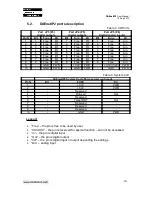
5.2.
DAEnetIP2 ports description
Table 3. I/O Ports
Port JP3 (P3)
digital outputs
Port JP4 (P5)
digital outputs
Port JP5 (P6)
(digital/analog inputs)
Pin N
Bit
Func
Dir
Bit
Func
Dir
Bit
Func
Dir
1
1
Free
I/O
1
Free
I/O
1
Free
Ain
2
2
Free
I/O
2
Free
I/O
2
Free
Ain
3
3
Free
I/O
3
Free
I/O
3
Free
Ain
4
4
Free
I/O
4
Free
I/O
4
Free
Ain
5
5
Free
I/O
5
Free
I/O
5
Free
Ain
6
6
Free
I/O
6
Free
I/O
6
Free
Ain
7
7
Free
I/O
7
Free
I/O
7
Free
Ain
8
8
Free
I/O
8
Free
I/O
8
Free
Ain
9
-
GND
PWR
-
+3.3V
PWR
-
+3.3V(Vref)
PWR
10
-
GND
PWR
-
GND
PWR
-
GND
PWR
Table 4. System port
DAEnetIP2 System Port JP6 (reserved, not used)
Pin N
Bit
FUNC
Dir
1
-
+3.3V
PWR
2
-
+3.3V
PWR
3
-
Reserved
-
4
-
Ping Led
Out
5
-
Reserved
-
6
-
Target RST
Out
7
-
Reserved
-
8
-
Reserved
-
9
-
Reserved
-
10
-
GND
PWR
Legend:
•
“Free” – the pin is free to be used by user.
•
“XXXXXX” - the pin is reserved for special function – can not be accessed.
•
“In” – the pin is digital input
•
“Out” – the pin is digital output
•
"I/O" – the pin is digital input or output depending the settings
•
“Ain” – analog input
-
10
-


