background image

Rev. A, March 2022 

Page 7   


                        SRT Operator’s Manual 


6.3


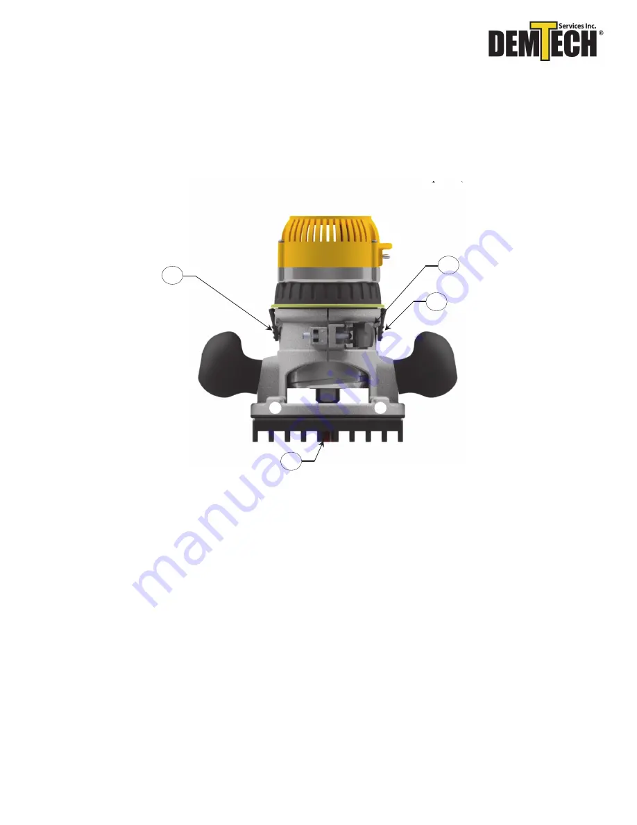
Setting Cut Depth 


a)


Unclamp 

Item 1, Figure 5.3

.   

b)


Press both levers (

Item 2, Figure 5.3

) in and adjust router base height. 

c)


Ensure the router bit is flush to bottom of the attachment plate (

Item 3, Figure 5.3

). 


Figure 5.3 


1


2


3


2


Summary of Contents for ART-0100/A SRT-0200/A

Page 1: ...SRT ART Removal Tool Operator s Manual Model Numbers ART 0100 A SRT 0200 A Revision A ...

Page 2: ... retrieval system or otherwise without prior written permission of DEMTECH Services Inc Notice Patents have been granted and or patent applications are pending or are in the process of preparation on all DEMTECH Services Inc developments The material in the manual is for informational purposes only and is subject to change without notice DEMTECH Services Inc assumes no responsibility for any error...

Page 3: ...AGE 2 2 1 Intended Use Page 2 2 2 Maintenance Page 2 3 GENERAL PRODUCT DATA PAGE 3 4 SITE PREPARATION PAGE 3 5 WHAT S INCLUDED PAGE 4 6 SETTING UP YOUR ART SRT REMOVAL TOOL PAGE 5 6 1 Attachment Plate Selection Page 5 6 2 Installing Attachment Plate Page 6 6 3 Setting Cut Depth Page 7 6 4 Changing Bits Page 8 7 FACTORY SERVICING PAGE 9 ...

Page 4: ...nt Observe all warnings in this manual WARNING 4 Make sure to disconnect all input power prior to performing any maintenance or repairs WARNING 5 This product is intended for operator attended operation only This product should never be left unattended at any time while the Grinder is on Incorrect use of the product will cause damage to the Stud Removal Tool and or the operator WARNING 6 Wear prop...

Page 5: ...p this manual with the SRT at or near the location where the SRT is being used so that it can be referred to quickly and easily The technician assigned to operate this SRT must have read through and become familiar with this manual particularly all safety information before operating the SRT No changes and or modifications shall be made to the SRT especially as it relates to safety 2 2 Maintenance...

Page 6: ...c strives to make our systems easy to use and built to last 4 Site Preparation Before proceeding with the unpacking and installation instructions in the following section s make sure the work site is prepared and ready to use the SRT The SRT has been designed to handle the roughest jobsite conditions prior to placing the SRT onto the liner area ensure there are no rocks or debris Failure to do so ...

Page 7: ... Page 4 SRT Operator s Manual 5 What s Included SRT 0200 A ART 0100 A 1X SRT 015 2X 22mm Wrench 3x 8 32 Screws 1X SRT 030 1X SRT 035 1x SRT 040 1X SRT 015 2X 22mm Wrench 3x 8 32 Screws 1x SRT 020 1X ART 010 1X ART 025 ...

Page 8: ...chment plate has been selected A labeled machine and transverse attachment plate has been provided This allows users to remove Studs in any direction See Figure 5 1 Contact DemTech Services to ensure you have the correct attachments for the job Figure 5 1 SRT 030 Transverse Direction SRT 035 Machine Direction ART 010 Transverse Direction ART 025 Machine Direction ...

Page 9: ...Rev A March 2022 Page 6 SRT Operator s Manual 6 2 Installing Attachment Plate a Install 3x screws Item 2 Figure 5 2 into router housing using a Phillips head screwdriver Figure 5 2 1 2 2 2 ...

Page 10: ...or s Manual 6 3 Setting Cut Depth a Unclamp Item 1 Figure 5 3 b Press both levers Item 2 Figure 5 3 in and adjust router base height c Ensure the router bit is flush to bottom of the attachment plate Item 3 Figure 5 3 Figure 5 3 1 2 3 2 ...

Page 11: ... Figure 5 4 to the ON position Note router shown without power cord Figure 5 4 6 4 Changing Bits a Prior to changing bits ensure no attachment plate is fastened to Router Utilize provided Wrench set to loosen the Router Bits collet Hold Item 1 Figure 5 5 and loosen Item 2 Figure 5 5 to release the Router Bit Figure 5 5 1 1 2 ...

Page 12: ...be detached and sent in for service Refer to the following step for preparing the V Plate for return Unless previous arrangements are made shipping charges and insurance are the responsibility of the customer Ship the packaged V Plate to DEMTECH Services Inc at DemTech Services Inc Ship to address 6414 Capitol Avenue Diamond Springs CA 95619 U S A ...

Page 13: ...ected to abuse accident or other abnormal conditions IF ANY FAULT DEVELOPS THE FOLLOWING STEPS SHOULD BE TAKEN 1 Notify DEMTECH Services Inc by calling 1 888 324 9353 Overseas customers should contact the local DEMTECH authorized service center Please be prepared with the model number serial number and full details of the difficulty Upon receipt of this information service data or shipping instruc...

Reviews: