www.deltapowersolutions.com
3 / 8
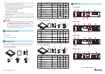
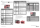
UPS202R2000B1B1
UPS302R2000B1B1
OUTPUT SOCKET
R
S-
23
2
MINI SLOT
IN P U T B R E A K E R
250V AC.20A
AC IN P U T
EXTERNAL BATT. CONNECTOR
48V DC 40A
OUTPUT SOCKET
R
S-
23
2
MINI SLOT
IN P U T B R E A K E R
250V AC.20A
AC IN P U T
EXTERNAL BATT. CONNECTOR
72V DC 40A
1
2
3
4
5
6
7
8
1
2
3
4
5
6
7
8
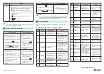
UPS102R2000B0B2
UPS202R2000B0B2
R
S-
23
2
MINI SLOT
INPUT BREAKER
250
V AC.10A
OUTPUT SOCKET
EXTERNAL BATT. CONNECTOR
24V DC 40A
R
S-
23
2
MINI SLOT
IN P U T B R E A K E R
250V AC.20A
AC IN P U T
AC IN P U T
EXTERNAL BATT. CONNECTOR
48V DC 40A
OUTPUT SOCKET(10A MAX. PER OUTLET)
1
2
3
4
6
5
8
7
1
2
3
4
6
7
8
5
UPS302R2000B0B2
R
S-
23
2
MINI SLOT
IN P U T B R E A K E R
250V AC.20A
AC IN P U T
EXTERNAL BATT. CONNECTOR
72V DC 40A
OUTPUT SOCKET(10A MAX. PER OUTLET)
1
2
3
7
4
6
5
8
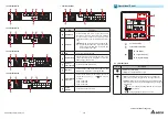
No.
Item
Functions
1
RS-232 Port
Communicates with a PC, so you can monitor
the status of the UPS. (UPSentry 2012 Software
is required. Please download it from http://www.
deltapowersolutions.com/en/mcis/software-center.
php).
NOTE:
Do not use the USB port and the RS-
232 port at the same time. If you connect the
USB cable to the USB port, the RS-232 port
will be disabled right away.
2
USB Port
3
Fan
Cools and ventilates the UPS.
4
Input Breaker
Prevents the UPS from damage caused by high
current and protects the utility power from further
damage when the UPS fails.
5
AC Input
(Input Socket)
Connects the UPS to the mains.
6
Mini Slot
Connects a Mini SNMP, a Mini Relay I/O or a Mini
MODBUS card (optional) to manage the UPS.
7
External Batt.
Connector
Connects the Delta external battery pack(s) to
extend back up time (+, -, and terminals are
included).
1 kVA : 24Vdc.40A
2 kVA : 48Vdc.40A
3 kVA : 72Vdc.40A
8
Output
Sockets
Connect the loads to the UPS.
6
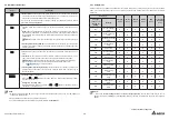
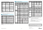
Operational Panel
ON
OFF
SETUP
Hz
KW
KVA
AH
MIN
MIN
ECO
V
V%
IN
SET IN OUT BATT
RUN TIME
°C
LOAD TEST
6.3 LCD Display
6.2 Multi-function Buttons
6.1 LED Indicators
6.4 7-segment Display
6.5 16-segment Display
1
1
2
3
2
3
6.1 LED Indicators
Icon(s)
Description
Indicates the output status.
z
z
ON
(green): Output;
OFF
: No output.
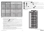
1.
ON
: The UPS detects an internal fault or an environmental
fault. The error code will appear on the 16-segment display.
2.
Flashing
: When the icon is flashing, it would be accompanied
with other icon(s) to indicate the according warning message(s).
For example:
a. (
Hz
KW
KVA
AH
MIN
V
%
SET IN OUT BATT
°C
LOAD
TEST
): There is no battery or battery replacement is required.
b. (
Hz
KW
KVA
AH
MIN
V
%
SET IN OUT BATT
°C
LOAD
TEST
): Overload.
c. (
MIN
V
IN RUN TIME
): Charging voltage is too high or too low.
Continue to the Next Page


