Delta Unisaw 36-841 Instruction Manual Download Page 29

29

OPERATING CONTROLS 

AND UNISAW ADJUSTMENTS

STARTING AND STOPPING 

THE SAW

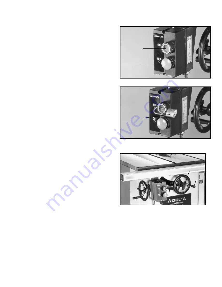
To apply power to the machine, push “ON” button (A) Fig.
106. To stop the machine, push “OFF” button (B).

Fig. 106

A

B

LOCKING SWITCH 

IN THE “OFF” POSITION

IMPORTANT: 

When the tool is not in use, the switch

should be locked in the OFF position using a padlock (A)
Fig. 107, with a 3/16" diameter shackle to prevent
unauthorized use.

Fig. 107

A

BLADE RAISING
MECHANISM

The saw blade is raised and lowered with the front
handwheel (A) Fig. 108. With the exception of hollow
ground blades, the blade should be raised 1/8" to 1/4"
above the top surface of the material being cut. With
hollow ground blades, the blade should be raised the
maximum to provide greater clearance. To raise the saw
blade, loosen lock knob (B) Fig. 108, and turn the
handwheel (A), clockwise. To lower the saw blade, turn
handwheel (A) counterclockwise.

The saw blade is locked at any height by turning the lock
knob (B) Fig. 108, clockwise. Due to the wedge action of
this locking device, only a small amount of force is
required to lock the blade raising mechanism securely.
Any added force merely puts unnecessary strain on the
locking device. Limit stops for raising or lowering are
permanently built into the mechanism and need no
further adjustment.

Fig. 108

D

C

B

A

E

BLADE TILTING MECHANISM

The blade tilting mechanism allows the blade to be tilted
up to 45 degrees to the right.

To tilt the saw blade to the desired angle, loosen lock
knob (D) Fig. 108, and turn handwheel (C). A pointer
indicates the angle of tilt on scale (E), which is marked in
one-degree increments. To lock the saw blade in the
desired angle of tilt, tighten lock knob (D).

IMPORTANT: ALWAYS LOCK THE BLADE IN
POSITION BEFORE APPLYING POWER TO THE SAW.

OVERLOAD PROTECTION

Your saw is supplied with overload protection. If the
motor shuts off or fails to start due to overloading
(cutting stock too fast, using a dull blade, using the saw
beyond its capacity, etc.) or low voltage, let the motor
cool three to five minutes. The overload will
automatically reset itself and the machine can then be
started again by pressing the “ON” button. 

IMPORTANT:

If the motor continually shuts off due to

overloading, the cause of overloading must be
corrected. If this happens, it is recommended that you
contact a qualified electrician.

Summary of Contents for Unisaw 36-841

Page 1: ...02 Copyright 2002 Delta Machinery To learn more about DELTA MACHINERY visit our website at www deltamachinery com For Parts Service Warranty or other Assistance please call 1 800 223 7278 In Canada ca...

Page 2: ...y to get caught in moving parts Nonslip footwear is recommended Wear protective hair covering to contain long hair 12 SECURE WORK Use clamps or a vise to hold work when practical It s safer than using...

Page 3: ...blade has come to a complete stop remove all debris 8 NEVER START THE MACHINE with the workpiece against the blade 9 HOLD THE WORKPIECE FIRMLY against the miter gauge or fence 10 NEVER run the workpie...

Page 4: ...by qualified service personnel and after reconnection the machine should comply with all local codes and ordinances WARNING IN ALL CASES MAKE SURE THE RECEPTACLE IN QUESTION IS PROPERLY GROUNDED IF YO...

Page 5: ...not use acetone gasoline or lacquer thinner for this purpose After cleaning cover the unpainted surfaces with a good quality household floor paste wax Figures 1 and 2 illustrate the saw and all loose...

Page 6: ...ter gage 16 Flat washer for miter gage handle 17 Handle for miter gage 18 Cap for miter gage handle 19 Dust chute adapter 20 10 x 1 2 hex washer head screws 8 21 Extension Wing 2 22 Hangers for rip fe...

Page 7: ...3 10 Angle brackets 3 11 Guide rail end caps 2 12 7 16 20 x 3 4 bolt lockwasher flat washer 3 13 1 4 20 x 5 8 bolt flat washer nut 4 14 3 8 16 x 1 bolt flat washer nut 2 15 3 8 16x2 bolt 2 16 Rail sto...

Page 8: ...washers 2 16 3 8 16 hex nuts 2 for fastening guide tube to front rail Fig 4 17 1 2 long hex screws 9 18 Lock washers 9 leg hardware Fig 5 19 Legs 2 20 5 8 long wood screws 8 8 21 1 4 20 x 1 1 2 long...

Page 9: ...ock knob F Fig 6B into threaded end of the shaft B Hand tighten lock knob at this time Do not over tighten see Blade Raising Mechanism Fig 6B ASSEMBLING EXTENSION WINGS Assemble the extension wings A...

Page 10: ...remove screw and fastener plate C Fig 12 Using a straight edge D Fig 13 check to see if the splitter bracket A is aligned with the inside blade flange B Check both the top and bottom of bracket A with...

Page 11: ...plitter P Fig 20 inside the splitter mounting bracket behind splitter fastener plate and screw C Push splitter down as far as possible making certain the bottom edge of splitter P is parallel with the...

Page 12: ...26 and recheck alignment 13 Holding the clear blade guard lower the saw blade and assemble the table insert E Fig 27 into the opening on the saw table Fig 23 Fig 24 A P B X Z Y Fig 25 Fig 26 Fig 27 E...

Page 13: ...E ADAPTER UNLESS A DUST COLLECTION SYSTEM IS USED IN CONJUNCTION WITH THE SAW FOR THE DUST CHUTE ADAPTER WILL RESTRICT THE GRAVITY FEED OPENING FOR SAW DUST REMOVAL MITER GAGE HOLDER AND WRENCH HOLDER...

Page 14: ...ers and hex nuts NOTE The shelf support bracket should be attached to the legs with the shelf support bracket facing the long end of the table board NOTE Height adjustments to the bracket will be made...

Page 15: ...le Z brackets J Fig 40 to the inside edge on right side of extension wing K as shown using three 7 16 20x 3 4 hex head screws lockwashers and flat washers L Place lockwasher washer z bracket onto scre...

Page 16: ...7 8 inch long wood screws Q Fig 47 CAUTION DO NOT OVER TIGHTEN TABLE MOUNTING SCREWS Over tighten ing screws in particle board may cause them to strip 13 Using a straight edge S Fig 46 make certain t...

Page 17: ...hex head of the bolts partially inserted in step 3 and 4 above Note The bolt heads on the saw table slide into the upper t slot B Fig 51 and the bolt head on the extension table slide into the lower...

Page 18: ...To attach rail stop to unifence as shown in Fig 58 7 Using a rubber mallet P Fig 57 or a hammer and a block of wood gently tap end cap R into both ends of the guide rail NOTE To avoid damage to the g...

Page 19: ...ush the handle B back in but do not rotate it 2 Place fence body A Fig 63 onto the guide rail as shown making sure clamp bracket is inserted into channel G on rail Notice that the clamp handle B is tu...

Page 20: ...h as a ruler D between the table and fence as shown Then tighten two lock knobs C Fig 66 Fig 67 Fig 68 Fig 69 C A B C A B C D FENCE OPERATION 1 Before operating fence make sure the fence is ad justed...

Page 21: ...ork is pushed along the fence it must have a straight edge and make solid contact with the table The saw blade guard must be used The guard has anti kickback fingers to prevent wood kickback and a spl...

Page 22: ...ve the fence A until the bottom front edge of the fence is in line with the edge of the miter gage slot as shown and push down on fence clamping lever C Check to see if the fence is parallel to the mi...

Page 23: ...e fence body B is completely fastened to the rail by pushing down on locking lever A Adjust further if necessary IMPORTANT AFTER ADJUSTING THE CLAMPING ACTION OF THE FENCE LOCKING HANDLE CHECK TO SEE...

Page 24: ...lade When using the fence as a cut off gage position the fence A to the front as shown in Fig 84 or purchase a 12 long fence B as shown in Fig 85 A typical operation using the 12 long fence B as a cut...

Page 25: ...ware at this time 2 Using template D Figures 89 and 90 to check and adjust front rail at both ends of the saw table as shown to make sure rail A is parallel with table surface and tighten rail mountin...

Page 26: ...SSEMBLING EXTENSION TABLE TO FRONT AND REAR RAILS 1 Place table assembly N Fig 95 in position between the two rails as shown Make sure end of table N is flush against extension wing P Using a straight...

Page 27: ...nd gently push fence onto rail B Fig 99 2 To move the fence along the guide rail lift up clamp lever A as shown in Fig 99 slide fence to desired position on rail and push down on clamp lever A as show...

Page 28: ...re the fence is parallel with the miter gage slot IMPORTANT VERY LITTLE MOVEMENT OF SCREWS D AND E IS NECESSARY TO ADJUST THE FENCE PARALLEL WITH THE MITER GAGE SLOT ADJUSTING CLAMPING ACTION OF FENCE...

Page 29: ...k the blade raising mechanism securely Any added force merely puts unnecessary strain on the locking device Limit stops for raising or lowering are permanently built into the mechanism and need no fur...

Page 30: ...shown Loosen locknut C and tighten or loosen adjusting screw D until head of screw D contacts casting on front trunnion when the blade is at 45 degrees to the table Then tighten locknut C Fig 109 Fig...

Page 31: ...g or loosening the three adjusting screws B Fig 115 with allen wrench supplied To rotate the miter gage loosen lock knob A Fig 115 and move the body of the miter gage C to the desired angle The miter...

Page 32: ...POWER SOURCE 2 Open motor cover door to gain access to the motor 3 Place a block of wood C Fig 118 between the motor and saw cabinet as shown NOTE It may be necessary to raise the saw arbor in order t...

Page 33: ...the work firmly against the miter gage and the table One of the rules in running a saw is that you never hang onto or touch a free piece of work Hold the supported piece not the free piece that is cu...

Page 34: ...and brought back along the outside edge of the fence The cut off stock remains on the table and is not touched with the hands until the saw blade is stopped unless it is a large piece allowing safe r...

Page 35: ...as shown NOTE THE OUTSIDE ARBOR FLANGE CAN NOT BE USED WITH THE MOULDING CUTTERHEAD TIGHTEN THE ARBOR NUT AGAINST THE CUTTERHEAD BODY DO NOT LOOSE THE OUTSIDE ARBOR FLANGE FOR IT WILL BE NEEDED WHEN...

Page 36: ...the two outside saws The teeth of the saws should be positioned so that the raker on one saw is beside the cutting teeth on the other saw The dado head set D Fig 133 is assembled to the saw arbor as s...

Page 37: ...ssory that can be used in place of the standard blade guard that is supplied with the Unisaw The Delta Model 34 976 Uniguard Blade Guard can be mounted to the Unisaw the Unisaw with a Jet Lock rip fen...

Page 38: ...ERE TO PUSH 1 4 WOOD CUT OFF HERE TO PUSH 1 2 WOOD NOTCH TO HELP PREVENT HAND FROM SLIPPING 1 2 SQUARES CONSTRUCTING A PUSH STICK When ripping work less than 4 inches wide a push stick should be used...

Page 39: ...lta s sole warranty and sets forth the customer s exclusive remedy with respect to defective products all other warranties express or implied whether of merchantability fitness for purpose or otherwis...

Page 40: ...s Angeles 3949A East Guasti Road Phone 909 390 5555 Fax 909 390 5554 San Leandro 94577 Oakland 3039 Teagarden Street Phone 510 357 9762 Fax 510 357 7939 FLORIDA Davie 33314 Miami 4343 South State Rd 7...

Reviews: