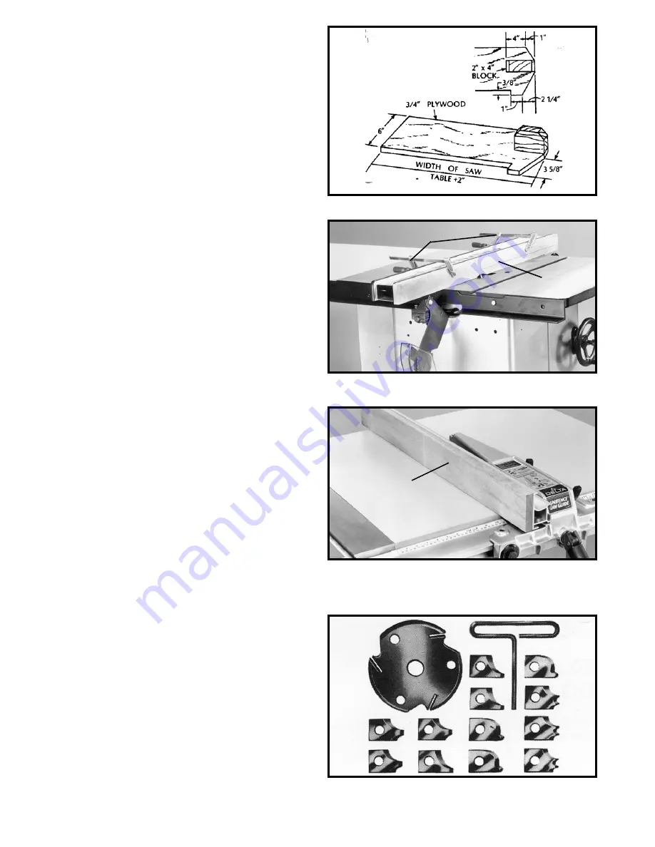
Delta UNISAW 34-801 Instruction Manual Download Page 20

20

Fig. 61

USING AUXILIARY WOOD 
FACING ON BIESEMEYER
RIP FENCE

It is necessary when performing special operations such
as moulding to add wood facing (A) Fig. 62, to one or
both sides of the rip fence, as shown. The wood facing is
attached to the fence with two clamps (B). 3/4 inch stock
is suitable for most work although an occasional job may
require 1 inch facing.

A wood facing should be used when ripping thin material
such as paneling to prevent the material from catching
between the bottom of the rip fence and the saw table
surface.

Fig. 62

B

A

Fig. 64

USING ACCESSORY
MOULDING CUTTERHEAD

Moulding is cutting a shape on the edge or face of the
work. Cutting mouldings with a moulding cutterhead in
the circular saw is a fast, safe and clean operation. The
many different knife shapes available make it possible for
the operator to produce almost any kind of mouldings,
such as various styles of corner moulds, picture frames,
table edges, etc.

The moulding head consists of a cutterhead in which can
be mounted various shapes of steel knives, as shown in
Fig. 64. Each of the three knives in a set is fitted into a
groove in the cutterhead and securely clamped with a
screw. The knife grooves should be kept free of sawdust,
which would prevent the cutter from seating properly.

USING AUXILIARY WOOD
FACING ON THE UNIFENCE

Fig. 63

It is necessary when performing special operations such
as when using the moulding cutterhead to add wood
facing (A) Fig. 63, to one side of the rip fence as shown.
The wood facing is attached to the fence with wood
screws through holes you drill in the fence. A suitable
stock size for most work is 3/4", although an occasional
job may require one inch facing.

A

When ripping boards longer than three feet, it is
recommended that a work support be used at the rear of
the saw to keep the workpiece from falling off the saw
table.

If the ripped work is less than 4 inches wide, a push stick
should always be used to complete the feed, as shown in
Fig. 60. The push stick can easily be made from scrap
material as explained in the section 

“CONSTRUCTING A

PUSH STICK.”

When ripping material under 2 inches in

width, a flat pushboard is a valuable accessory since
ordinary type sticks may interfere with the blade guard.
That flat pushboard can be made as shown in Fig. 61.

Summary of Contents for UNISAW 34-801

Page 1: ...4 806 34 814 36 812 PART NO 422 04 651 0064 01 15 02 Copyright 2002 Delta Machinery To learn more about DELTA MACHINERY visit our website at www deltamachinery com For Parts Service Warranty or other...

Page 2: ...y to get caught in moving parts Nonslip footwear is recommended Wear protective hair covering to contain long hair 12 SECURE WORK Use clamps or a vise to hold work when practical It s safer than using...

Page 3: ...blade has come to a complete stop remove all debris 8 NEVER START THE MACHINE with the workpiece against the blade 9 HOLD THE WORKPIECE FIRMLY against the miter gauge or fence 10 NEVER run the workpie...

Page 4: ...vice personnel and after reconnection the machine should comply with all local codes and ordinances 3 Permanently connected machines This machine should be connected to a grounded metal permanent wiri...

Page 5: ...12 240 50 100 16 AWG 10 12 240 100 200 14 AWG 10 12 240 200 300 12 AWG 12 16 240 up to 50 14 AWG 12 16 240 50 100 12 AWG 12 16 240 GREATER THAN 100 FEET NOT RECOMMENDED FIVE HORSEPOWER MOTORS The mot...

Page 6: ...r is in the 90 degree position and remove the styrofoam packing from inside the saw cabinet Tighten locking knob Fig 1 UNISAW 1 Unisaw 2 Switch shown with a LVC switch 3 Motor cover 4 Blade guard and...

Page 7: ...OFF BUTTONS A LVC STARTER HAS RECTANGLE ON AND OFF BUTTONS NOTE FOR GPE STARTER BOX When assembling the left extension wing do not install the front screw and washer at this time it will be installed...

Page 8: ...x 1 2 hex head screw into the hole B Fig 7 in the cabinet Repeat this process for the two remaining screws 2 Line up the three tapped holes C Fig 7 in the starter box with the screws and secure the s...

Page 9: ...ER ASSEMBLY CAUTION DISCONNECT MACHINE FROM POWER SOURCE 1 Remove the table insert Fig 14 Raise the saw arbor by turning the locking handle on the front of the saw counter clockwise and then turn the...

Page 10: ...ough slot in rear of saw and into hole in rear trunnion H Fasten support rod G to trunnion with star washer and hex nut J Fig 19 NOTE Thread nut J Fig 19 onto threads of support rod G as much as possi...

Page 11: ...de guard assembly P Fig 24 to bracket M using a 5 16 18x1 hex head screw V and 5 16 flat washer 10 IMPORTANT The splitter P Fig 25 features a notch W cut into the top edge Raise the front of the clear...

Page 12: ...28 and 29 make certain saw blade B Fig 28 and splitter P Fig 29 are 90 degrees to the table surface Once you are certain the splitter is aligned to the saw blade and table tighten all splitter mountin...

Page 13: ...metal screws NOTE DO NOT MOUNT THE DUST CHUTE ADAPTER UNLESS A DUST COLLECTION SYSTEM IS USED IN CONJUNCTION WITH THE SAW FOR THE DUST CHUTE ADAPTER WILL RESTRICT THE GRAVITY FEED OPENING FOR SAW DUST...

Page 14: ...e is required to lock the blade raising mechanism securely Any added force merely puts unnecessary strain on the locking device Limit stops for raising or lowering are permanently built into the mecha...

Page 15: ...s shown Loosen locknut C and tighten or loosen adjusting screw D until head of screw D contacts casting on front trunnion when the blade is at 45 degrees to the table Then tighten locknut C Fig 42 Fig...

Page 16: ...ning or loosening the three adjusting screws B Fig 48 with allen wrench supplied To rotate the miter gage loosen lock knob A Fig 48 and move the body of the miter gage C to the desired angle The miter...

Page 17: ...ROM POWER SOURCE 2 Open motor cover door to gain access to the motor 3 Place a block of wood C Fig 51 between the motor and saw cabinet as shown NOTE It may be necessary to raise the saw arbor in orde...

Page 18: ...at you never hang onto or touch a free piece of work Hold the supported piece not the free piece that is cut off The feed in cross cutting continues until the work is cut in two and the miter gage and...

Page 19: ...the table Since the work is pushed along the fence it must have a straight edge and make solid contact with the table The saw guard must be used The guard has anti kickback fingers to prevent wood ki...

Page 20: ...as shown in Fig 64 Each of the three knives in a set is fitted into a groove in the cutterhead and securely clamped with a screw The knife grooves should be kept free of sawdust which would prevent th...

Page 21: ...It is necessary when using the moulding cutterhead to add wood facing C to the face of the rip fence as shown in Fig 68 The wood facing is attached to the biesemeyer fence with two clamps as shown re...

Page 22: ...oove A 1 4 groove is cut by using the two outside saws The teeth of the saws should be positioned so that the raker on one saw is beside the cutting teeth on the other saw The dado head set D Fig 72 i...

Page 23: ...ntact with the fence and table and help prevent kickbacks Clamp the featherboards to the fence and table so that the leading edge of the featherboards will support the workpiece until the cut is compl...

Page 24: ...ERE TO PUSH 1 4 WOOD CUT OFF HERE TO PUSH 1 2 WOOD NOTCH TO HELP PREVENT HAND FROM SLIPPING 1 2 SQUARES CONSTRUCTING A PUSH STICK When ripping work less than 4 inches wide a push stick should be used...

Page 25: ...me Shop Fence Systems up to 52 for mounting the No 34 976 Delta Uniguard Blade Guard Mounting hardware included Fig 77 Biesemeyer T Square Table Saw Blade Guard System The Biesemeyer Model 78 960 Bies...

Page 26: ...lta s sole warranty and sets forth the customer s exclusive remedy with respect to defective products all other warranties express or implied whether of merchantability fitness for purpose or otherwis...

Page 27: ...27 NOTES...

Page 28: ...s Angeles 3949A East Guasti Road Phone 909 390 5555 Fax 909 390 5554 San Leandro 94577 Oakland 3039 Teagarden Street Phone 510 357 9762 Fax 510 357 7939 FLORIDA Davie 33314 Miami 4343 South State Rd 7...

Reviews: