Delta Unifence 36-902 Instruction Manual Download Page 5

5

5.

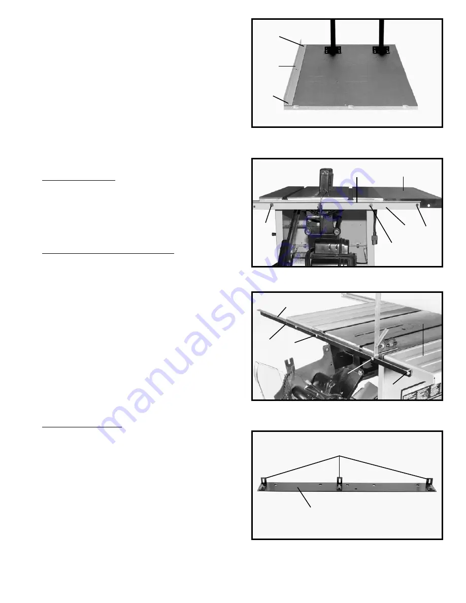
Fasten the front table support (F) Fig. 9, to the

bottom of the table as shown using two #8x7/8" long
wood screws (H) and (I) supplied. 

NOTE: 

The vertical flange, on the table board support

(F), should be flush with the front edge of the table
board.

NOTE:

The slots closer to the angles in the support (F)

should be against the table. 

NOTE:

Screws (H) and (I) Fig. 9 should not be

completely tightened to the table board at this time.
Screw (I) will have to be removed later. 

NOTE:

Make certain the end of the table support does

not extend out past the table. 

CAUTION: DO NOT OVER-TIGHTEN MOUNTING
SCREWS. 

Over-tightening screws in particle board may

cause them to strip.

FOR UNISAWS ONLY

6.

Fasten the rear table support (A) Fig. 10, to the saw

table. Insert a 3/8-24x5/8" hex head screw (B), through hole
in rear support and thread screw into tapped hole in table.
Repeat this process for the remaining hole. Tighten screws
securely. 

NOTE: FLAT EDGE (D) Fig. 10 AND FIG. 10A, OF

REAR TABLE SUPPORT WILL FACE UPWARD.

FOR 10" CONTRACTORS SAWS ONLY

6.

Fasten the rear table support (A) Fig. 10, to the saw

table. Insert a 3/8-16x1" hex head screw (B), through hole in
rear support and table, place a 3/8 washer onto the screw
and thread a 3/8-16 hex nut onto screw and tighten
securely. Repeat this process for the remaining hole. 

NOTE:

FLAT EDGE (D) Fig. 10 AND FIG. 10A, OF REAR TABLE
SUPPORT WILL FACE UPWARD.

7.

If your saw is equipped with a cast iron wing as shown

at (I) Fig. 10. which has a smooth surface, hole (C) Fig. 10 is
not used, proceed to 

step 8

. If your saw has a sheet metal

wing as shown at (W) Fig. 10A, with a ribbed surface, the
rear table support will be fastened through hole (C) Fig. 10A
as follows. Insert a 3/8-16x1" hex head screw through hole
(C) and the sheet metal extension wing, place a 3/8" washer
on the screw, thread a 3/8-16 hex nut on screw, and tighten
securely.

FOR ALL TABLE SAWS

8.

Assemble the three brackets (J) to the table adapter

plate (K) using the three 1/4-20x3/4" carriage bolts, nuts and
washers, as shown in Fig. 11. 

NOTE:

The long leg of the

brackets (J) should be against the adapter plate (K) as
shown. Do not completely tighten brackets (J) to adapter
plate (K) at this time.

Fig. 9

Fig. 11

J

K

Fig. 10

A

B

B

F

H

I

C

D

Fig. 10A

W

C

D

B

B

A

I

Summary of Contents for Unifence 36-902

Page 1: ...36 902 PART NO 422 27 655 0068 02 14 03 Copyright 2003 Delta Machinery To learn more about DELTA MACHINERY visit our website at www deltamachinery com For Parts Service Warranty or other Assistance p...

Page 2: ...ket 6 Table Adapter Plate 7 Table Leg 2 8 Rear table support bracket 9 1 4 20x2 Flip stop bolt 10 Flip stop bracket 11 5 16 18x1 Hex head bolt 12 Flip stop 13 Flip stop knob 14 1 4 20 Nut 15 Flip stop...

Page 3: ...3 Fig 2 Fig 3...

Page 4: ...the 36 902 30 Unifence Fig 4 Fig 5 4 Insert foot adapter T Fig 6 into the bottom of each leg A Assemble the 3 8 jam nut V approximately 3 4 of the way onto leveling screw W Thread the leveling screw...

Page 5: ...AWS ONLY 6 Fasten the rear table support A Fig 10 to the saw table Insert a 3 8 16x1 hex head screw B through hole in rear support and table place a 3 8 washer onto the screw and thread a 3 8 16 hex n...

Page 6: ...plate B and or saw table NOTE Do not drill any hole to fasten adapter plate B Fig 12 to the saw table that will be located less than two inches from either end of the adapter plate Before tightening t...

Page 7: ...he ON OFF switch is mounted to the extension wing proceed with step 1 if not proceed to step 2 1 Remove the screw A Fig 18 that attaches the ON OFF switch to the sheet metal wing Insert a 3 8 16x1 hex...

Page 8: ...SAWS OTHER THAN DELTA 3 Drill two 7 16 holes in the front of the table 1 18 from the top of the table and approximately 2 in from the right and left side of the table Insert two 3 8 24x1 hex head bol...

Page 9: ...me distance is maintained from the top surface of the extension table K to the top surface of the guide rail C Move the front table support L Fig 27 against the guide rail C and tighten the 1 4 20 nut...

Page 10: ...be repositioned in the rail slot to allow the flip stop to retract fully If bolt F needs to be repositioned just slide the bolt out of the rail and turn the head of the bolt one third of a turn one fl...

Page 11: ...fence body Turn handle B Fig 32 if necessary 2 Place fence body A Fig 35 onto the guide rail as shown making sure clamp bracket is inserted into channel G on rail Notice that the clamp handle B is tur...

Page 12: ...perations the bottom of the fence should be positioned slightly above the table surface Loosen two lock knobs C Fig 40 and place a thin object such as a scale D between the table and fence as shown Th...

Page 13: ...e fence is in the horizontal position and witness line C indicates the distance the fence is away from the blade when the fence is in the vertical position If it is necessary to adjust cursor D make a...

Page 14: ...fter which the work is lifted and brought along the outside edge of the fence The cut off stock remains on the table and is not touched with the hands until the saw blade is stopped unless it is a lar...

Page 15: ...is 90 degrees to the table place a square B on the table with one end of the square against the fence as shown If an adjustment is necessary tighten or loosen one of two screws C or D until the fence...

Page 16: ...ly be moved to the left side of the saw table USING THE FENCE AS A CUT OFF GAUGE The fence can be used as a cut off gage when cross cutting a number of pieces to the same length IMPORTANT When using t...

Page 17: ...s such as when using the moulding cutterhead to add wood facing A Fig 59 to one side of the rip fence as shown The wood facing is attached to the fence with wood screws through holes drilled in the fe...

Page 18: ...ERE TO PUSH 1 4 WOOD CUT OFF HERE TO PUSH 1 2 WOOD NOTCH TO HELP PREVENT HAND FROM SLIPPING 1 2 SQUARES CONSTRUCTING A PUSH STICK When ripping work less than 4 inches wide a push stick should be used...

Page 19: ...lta s sole warranty and sets forth the customer s exclusive remedy with respect to defective products all other warranties express or implied whether of merchantability fitness for purpose or otherwis...

Page 20: ...Southern Avenue Suite 105 Phone 602 437 1200 Fax 602 437 2200 CALIFORNIA Ontario 91761 Los Angeles 3949A East Guasti Road Phone 909 390 5555 Fax 909 390 5554 San Leandro 94577 Oakland 3039 Teagarden...

Reviews: