Delta ShopMaster MS250 Instruction Manual Download Page 10

10

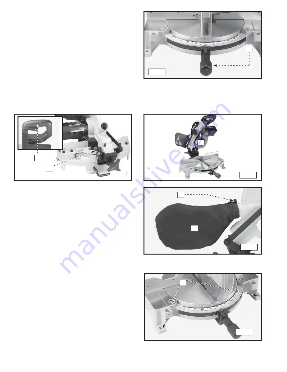
FASTENING THE MACHINE TO A SUPPORTING SURFACE

Before operating your compound miter saw, make sure that it 
is firmly mounted to a sturdy workbench or other supporting 
surface. Four holes are provided, two of which are shown at 
(A) Fig. 10.

When frequently moving the saw from place to place, mount 
the saw on a 3/4" piece of plywood, and clamp the plywood 
to a supporting surface with “C” clamps.

2.  Rotate the table to the left until the index stop engages 

with the 90° positive stop (Fig. 6). Tighten the table lock 
handle (A).

1.  Push down on handle (A), Inset, Fig. 7. Pull out the cuttinghead lock knob (B).
2.  Move the cuttinghead (C) to the up position (Fig. 8).

ATTACHING THE DUST BAG

Squeeze the spring clips (A) Fig. 9 of the dust bag (B) and clip 
the dust bag (B) over the ribs of the dust chute.

MOVING CUTTINGHEAD TO THE UP POSITION

Fig. 6

A

Fig. 7

Fig. 8

A

B

C

Fig. 9

A

B

A

Fig. 10

Summary of Contents for ShopMaster MS250

Page 1: ...ART NO A05737_01 24 06_RevB Copyright 2006 Delta Machinery ESPA OL P GINA 23 To learn more about DELTA MACHINERY visit our website at www deltamachinery com For Parts Service Warranty or other Assista...

Page 2: ...be modified and or used for any application other than for which it was designed If you have any questions relative to its application DO NOT use the product until you have written Delta Machinery an...

Page 3: ...EMS The symbols below are used to help you recognize this information SAFETY GUIDELINES DEFINITIONS SOME DUST CREATED BY POWER SANDING SAWING GRINDING DRILLING AND OTHER CONSTRUCTION ACTIVITIES contai...

Page 4: ...prevent injury 11 REMOVE ADJUSTING KEYS AND WRENCHES BEFORE STARTING THE MACHINE Tools scrap pieces and other debris can be thrown at high speed causing injury 12 USE THE RIGHT MACHINE Don t force a...

Page 5: ...ling the saw toward you can cause the saw to kick upward and toward you 17 WHEN USING A SLIDING MITER SAW AS A REGULAR MITERSAW LOCKTHESLIDEMECHANISMINPLACE If the slide mechanism is not locked the sa...

Page 6: ...ed electrician Improper connection of the equipment grounding conduc tor can result in risk of electric shock The conductor with insulation having an outer surface that is green with or without yellow...

Page 7: ...dersized cord will cause a drop in line voltage resulting in loss of power and overheating Fig D 1 shows the correct gauge to use depending on the cord length If in doubt use the next heavier gauge Th...

Page 8: ...RED Supplied 5mm hex wrench 1 2 Blade wrench Not supplied Phillips head screw driver A square to make adjustments ASSEMBLY TIME ESTIMATE Assembly time for this product will be about 30 minutes UNPACKI...

Page 9: ...the hole in the bevel pointer C Fig 3 with the hole D in the back of the base 3 Insert the M5x 8x10mm pan head screw with washer B Fig 3 through the hole in the bevel pointer C Thread the screw into t...

Page 10: ...od and clamp the plywood to a supporting surface with C clamps 2 Rotate the table to the left until the index stop engages with the 90 positive stop Fig 6 Tighten the table lock handle A 1 Push down o...

Page 11: ...e provided in the base of the miter saw enabling you to use the clamp A Fig 12 on either the right or left hand side of the saw blade Keep your hands out of path of saw blade If necessary clamp the wo...

Page 12: ...andle A Fig 15 and move the control arm until the bottom of the index lever B engages into one of the positive stops four of which are shown at C Tighten the lock handle A To disengage the positive st...

Page 13: ...g Refer to the CUTTING CROWN MOULDING section of this manual A rear support bar A Fig 21 is provided to prevent the machine from tipping to the rear when the cuttinghead returns to the up position For...

Page 14: ...e fence A and the other end against the blade 2 To adjust loosen the four screws C Fig 25 and adjust fence 90 degrees to the blade Tighten the four screws C 1 You can limit the downward travel of the...

Page 15: ...P Fig 31 loosen the screw H and adjust pointer P Tighten the screw H securely 8 These positive stops enable you to rapidly position the blade at the 90 and 45 bevel angle to the table A S Fig 29 Fig...

Page 16: ...freehand cutting wood that is not held firmly against the fence and table Holes are provided in the fence to attach an auxiliary fence A Fig 34 This auxiliary fence is constructed of straight wood app...

Page 17: ...A2 2 A standard 2 x 6 can be cut in the 90 straight cut off position in one pass Fig A3 3 Cutting a standard 4 x 4 can be accomplished with one pass Fig A4 4 This machine has the capacity to accuratel...

Page 18: ...cal because the distance from the top of the 2 x 4 s A to the miter saw table varies from saw to saw In most cases standard 2 x 4 s C can used If these are too high cut the 2 x 4s C to provide this he...

Page 19: ...gle quickly The saw blade is already tilted to the 33 86 left bevel position from the previous cut 5 Place the crown moulding on the table with the WALL EDGE of the crown moulding against the fence an...

Page 20: ...e blade flange F and the saw blade from the saw arbor 5 Attach the new saw blade making certain that the teeth of the saw blade are pointing down Fig 47 Place the outside blade flange F Fig 45 on the...

Page 21: ...or after a new set of brushes has been installed After the first check examine them after about 10 hours of use until a replacement is necessary To inspect the brushes KEEP MACHINE CLEAN Periodically...

Page 22: ...purchase of the product within two years and provides Delta with reasonable opportunity to verify the alleged defect by inspection For all refurbished Delta product the warranty period is 180 days De...

Page 23: ...no ser responsable en ninguna circunstancia de los da os incidentales o emergentes que se produzcan como resultado de productos defectuosos Esta garant a es la nica garant a de Delta y establece el r...

Reviews: