1
.
3
.
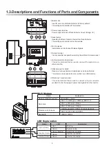
Descriptions and Functions of Parts and Components
POWER IN
5V
1
4
2 3
6
8
7
5
①
MICRO SD
Use SD card to reset Data Collector to factory default.
The settings and records will be deleted.
②
Power supply terminal
Power supply terminal of Data Collector. (Input Voltage: 5V)
③
Reset button
Resetting the Data Collector. Restart the Data Collector.
The settings and records will not be deleted.
④
Wi-Fi antenna
Install antenna to Enhance Wireless Signals.
⑤
Extend terminal
It is also possible to expand the matching Power Meter for measurement.
⑥
LAN terminal (RJ-45 terminal)
This is the terminal that is used to connect the system to an
ethernet cable.
⑦
USB terminal (for USB)
Reserve of various data and maintenance
can be performed.
*
Customers are requested to procure their own USB memory.
⑧
RS-485 (a 16-pin terminal)
This is the terminal that is used to connect a 16-pin connector
provided, to link the supply of power and signals from the Inverter.
LED Explanation
LED
Explanation
Green
Green (blinking)
Green
Green
Red
Name
Internet Comm
Inverter Comm
Modulation techniques
Bandwidth
Explanation
IEEE 802.11 b/g/n
802.11n 6.5Mbps to 150Mbps (MCS 0-7)
802.11g 6Mbps to 54Mbps
802.11b 1Mbps to 11Mbps
OFDM with BPSK, QPSK, 16-QAM, 64-QAM
802.11b with CCK and DSSS
20MHz/ 40MHz
Name
Network standard support
Data rates
Wi-Fi Module
System ready.
Searching inverters.
Inverter connected.
Internet connected.
Booting.
Stytem Ready
8
Summary of Contents for PPM DC1_100 Series
Page 25: ...20210223 ...


