65
Ultron NT Series
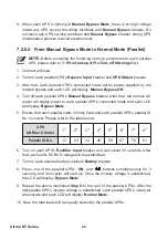
9. When each UPS is running in
Manual Bypass Mode
, there is no high voltage
inside any UPS except the wiring terminals and
Manual Bypass
breaker. Do
not touch any UPS’s wiring terminals and
Manual Bypass
breaker during UPS
maintenance process to avoid electric shock.
7.2.6.2 From Manual Bypass Mode to Normal Mode (Parallel)
NOTE :
Before executing the following start-up procedures to each parallel
UPS, please refer to
3UH6WDUWXS 3UH7XUQR௺:DUQLQJV
¿UVW
1. Connect all fuses.
2. Turn on each parallel UPS’s
Reserve Input
breaker and
UPS Output
breaker.
3. After that, each parallel UPS’s connected loads will be power-supplied by the
manual bypass and each LCD will display ‘
Manual Bypass ON
’.
7XUQRႇHDFKSDUDOOHO836¶V
Manual Bypass
breaker. After that, the reserve AC
power will supply power to each parallel UPS’s connected loads and each LCD
will display ‘
Bypass Mode
’.
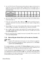
(QVXUHWKDWHDFKSDUDOOHOFDEOHLV¿UPO\¿[HGDQGHDFKSDUDOOHO836¶VSDUDOOHO,'
No. is correct. Please refer to the table below.
UPS
(At Max. 8 Units)
1
st
2
nd
3
rd
4
th
5
th
6
th
7
th
8
th
Parallel ID No.
12
23
34
45
56
67
78
81
6. Turn on each UPS’s
5HFWL¿HU,QSXW
breaker and wait about 30 seconds. After
that, each unit’s DC BUS voltage will be established.
7. Turn on each external battery cabinet’s
Battery
breaker.
8. Press one of the parallel UPSs’ ‘
ON
’ and ‘
’ buttons simultaneously for 3
seconds, and its inverter will start up. Once the inverter voltage is established,
the LCD will display ‘
Bypass Mode
’.
9. Repeat the above-mentioned
Step 8
to the rest of the parallel UPSs. After the
last parallel UPS’s inverter voltage is established, each parallel UPS’s contactor
will activate and each LCD will display ‘
Normal Mode
’.
10. Now, the total loads will be equally shared by the parallel UPSs.


