background image


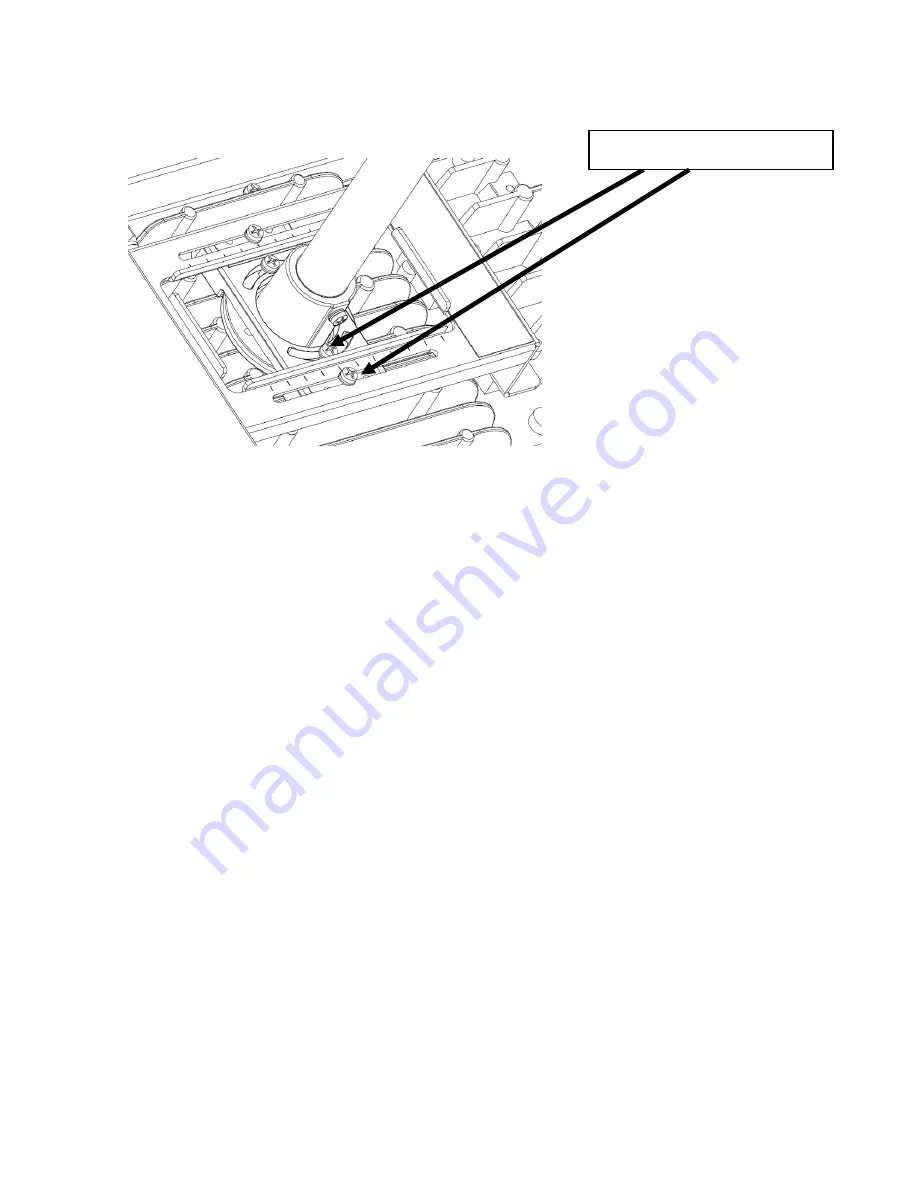
3.  The fixture should already be factory set for correct balance and orientation. If adjusting balance or 

orientation is necessary, make corrections using the adjustment screws in the locations shown


4.  Make wire connections inside the junction box according to the following color wires : 

  Green wire connects to Safety Ground.   

  White wire connects to Neutral.   

  Black wire connects to Live 


Adjustment screws


Summary of Contents for High Bay Luminaire Series

Page 1: ...his luminaire must be adequately grounded for protection against shock hazards and to assure proper operation Disconnect power before servicing Suspend from adequate structure that can safely support...

Page 2: ...3 To make electrical connections attach the lead wires according to the colors below Green wire connects to Safety Ground White wire connects to Neutral Black wire connects to Live 4 The fixture shoul...

Page 3: ...ON The fixture mounting receiver is threaded for 3 4 NPT pipe 1 Feed the power cable through the conduit and into the junction box Attach the fixture to the conduit 2 Insert set screw in order to secu...

Page 4: ...ce or orientation is necessary make corrections using the adjustment screws in the locations shown 4 Make wire connections inside the junction box according to the following color wires Green wire con...

Page 5: ...and T 2 0 min washer 2 Loosen the M10 and M4 screw and tilt the luminaire to the determinded direction If determinded fixed the Screw 3 Connect power cable conductors as follows Green wire connects t...

Page 6: ...ircraft cable assemblies to the luminaire with two aircraft cable assembly as shown below Notes a The assembly location must be shown below b Do not exceeded angle greater than a 30 between the cables...

Page 7: ...nnects to Safety Ground White wire connects to Neutral Black wire connects to Live SAFETY CABLE INSTALLATION 1 Attach one end of the safety cable through the hole between the fin on the luminarie 3 At...

Page 8: ...ing Cable that was secured by a wire grip when shipped The dimming cable can be identified by the marking on the driver power supply 2 Remove appropriate length of the dimming cable jacket and cut off...

Reviews: