background image

Use proper extension cords. Make sure your extension cord is in good condition and is a 3-wire extension cord which
has a 3-prong grounding type plug and matching receptacle which will accept the machine’s plug. When using an
extension cord, be sure to use one heavy enough to carry the current of the machine. An undersized cord will cause
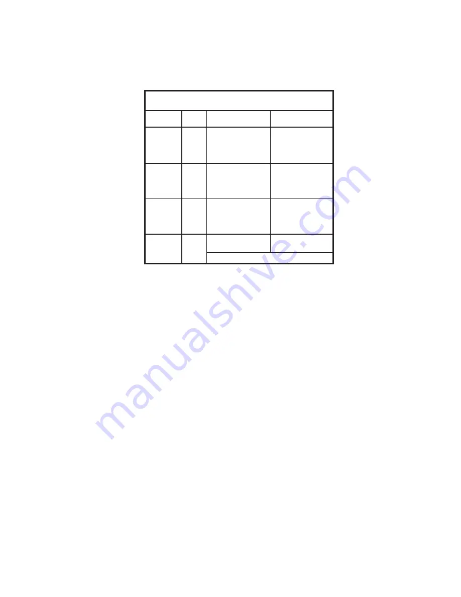
a drop in line voltage, resulting in loss of power and overheating. Fig. D, shows the correct gauge to use depending
on the cord length. If in doubt, use the next heavier gauge. The smaller the gauge number, the heavier the cord.

EXTENSION CORDS

OPERATING INSTRUCTIONS

FOREWORD

The Delta ShopMaster Model SA350 has a large 18" diameter cast-iron table, to support large workpieces. The
machine has a heavy-duty motor assembly, which features a 1/4 H.P. induction motor with direct drive for quiet, and
smooth operation.

UNPACKING AND CLEANING

Carefully unpack the machine and all loose items from the shipping container(s). Remove the protective coating from
all unpainted surfaces. This coating may be removed with a soft cloth moistened with kerosene (do not use acetone,
gasoline or lacquer thinner for this purpose). After cleaning, cover the unpainted surfaces with a good quality household
floor paste wax.

NOTICE: THE MANUAL COVER PHOTO ILLUSTRATES THE CURRENT

PRODUCTION MODEL.  ALL OTHER ILLUSTRATIONS ARE REPRESENTATIVE

ONLY AND MAY NOT DEPICT THE ACTUAL COLOR, LABELING OR

ACCESSORIES AND MAY BE INTENDED TO ILLUSTRATE TECHNIQUE ONLY.

5

Fig. D

MINIMUM GAUGE EXTENSION CORD

RECOMMENDED SIZES FOR USE WITH STATIONARY ELECTRIC MACHINES

Ampere

Total Length

Gauge of

Rating

Volts

of Cord in Feet

Extension Cord

0-6

120

up to 25

18 AWG

0-6

120

25-50

16 AWG

0-6

120

50-100

16 AWG

0-6

120

100-150

14 AWG

6-10

120

up to 25

18 AWG

6-10

120

25-50

16 AWG

6-10

120

50-100

14 AWG

6-10

120

100-150

12 AWG      

10-12

120

up to 25

16 AWG

10-12

120

25-50

16 AWG

10-12

120

50-100

14 AWG

10-12

120

100-150

12 AWG

12-16

120

up to 25

14 AWG

12-16

120

25-50

12 AWG

12-16

120

GREATER THAN 50 FEET NOT RECOMMENDED

Summary of Contents for B.O.S.S. SA350

Page 1: ...NO 906118 06 15 02 Copyright 2002 Delta Machinery ESPAÑOL PÁGINA 13 To learn more about DELTA MACHINERY visit our website at www deltamachinery com For Parts Service Warranty or other Assistance please call 1 800 223 7278 In Canada call 1 800 463 3582 33952 RTD10000124AA ...

Page 2: ...ry to get caught in moving parts Nonslip footwear is recommended Wear protective hair covering to contain long hair 12 SECURE WORK Use clamps or a vise to hold work when practical It s safer than using your hand and frees both hands to operate tool 13 DON T OVERREACH Keep proper footing and balance at all times 14 MAINTAIN TOOLS IN TOP CONDITION Keep tools sharp and clean for best and safest perfo...

Page 3: ... plenty of room for handling and supporting workpiece 12 WHEN installing sanding drums washers etc be sure they are tight without any excessive play 13 ALWAYS feed workpiece against the direction of the sanding drum rotation 14 CLEAR all debris from table before sanding the workpiece 15 MAKE CERTAIN that workpiece is properly supported Use extra caution when sanding small pieces 16 DO NOT sand pie...

Page 4: ...apter should be used only until a properly grounded outlet can be installed by a qualified electrician The green colored rigid ear lug and the like extending from the adapter must be connected to a permanent ground such as a properly grounded outlet box Whenever the adapter is used it must be held in place with a metal screw NOTE In Canada the use of a temporary adapter is not permitted by the Can...

Page 5: ...l loose items from the shipping container s Remove the protective coating from all unpainted surfaces This coating may be removed with a soft cloth moistened with kerosene do not use acetone gasoline or lacquer thinner for this purpose After cleaning cover the unpainted surfaces with a good quality household floor paste wax NOTICE THE MANUAL COVER PHOTO ILLUSTRATES THE CURRENT PRODUCTION MODEL ALL...

Page 6: ...ER PARTS Fig 2 1 Bench Oscillating Spindle Sander 2 Spindle Adapter 3 1 I D Table Insert 4 1 3 4 O D Drum Washer 5 Arbor Screw 6 3 4 Sanding Drum 3 4 Abrasive Sleeve 7 3 16 Allen Wrench 8 1 2 Socket Wrench 9 Dust Bag 1 2 3 4 5 6 7 8 9 ...

Page 7: ...screw not shown 3 Carefully place the machine on its side Fig 6 Attach the spindle adapter B Fig 6 to the motor shaft C by turning the spindle adapter counterclockwise on the shaft NOTE Motor shaft has a left hand thread 4 Place a 7 16 open end wrench D Fig 7 not supplied on the flats of spindle adapter B Insert 3 16 Allen wrench E Fig 8 supplied into socket head screw located where the plug A Fig...

Page 8: ...top surface 4 Compartments H Fig 12 on the sides of the sander can be used for storing work pieces or accessories Fig 10 A B C D E F G Fig 11 F D G Fig 12 H H C G DUST BAG 1 A 1 1 2 I D dust chute A Fig 13 is supplied with the spindle sander to accept the dust bag 2 To attach the dust bag B Fig 14 to the dust chute A squeeze the spring clamp on the dust bag and slide it over the dust chute Release...

Page 9: ...e the sander is running it can be turned OFF once but cannot be restarted without inserting the switch toggle A Fig 19 B CHANGING ABRASIVE SLEEVES AND SANDING DRUMS 1 DISCONNECT MACHINE FROM POWER SOURCE 2 Remove table insert A Fig 20 3 Use the supplied socket wrench B Fig 20 to remove the arbor screw turn screw clockwise Remove the abrasive sleeve C with the sanding drum from the spindle assembly...

Page 10: ... inside the center of bracket D To adjust loosen the two locknuts E Fig 23 Tighten or loosen the two adjusting screws F as necessary until the shaft C is centered inside the bracket D with the adjustment screws F contacting the shaft Tighten the two locknuts E Fig 23 5 Attach the case with the four screws removed in STEP 3 Fig 22 A A Fig 23 B E F F C D OPERATION Fig 24 illustrates sanding inside c...

Page 11: ...uld be checked and changed To gain access to the gear housing 1 DISCONNECT MACHINE FROM POWER SOURCE 2 Turn the machine over and loosen the two screws A Fig 25 and remove the cover B 3 Remove the old grease and repack the gears with new grease 4 Replace the cover Fig 25 A B ...

Page 12: ...a s sole warranty and sets forth the customer s exclusive remedy with respect to defective products all other warranties express or implied whether of merchantability fitness for purpose or otherwise are expressly disclaimed by Delta Printed in U S A PARTS SERVICE OR WARRANTY ASSISTANCE All Delta Machines and accessories are manufactured to high quality standards and are serviced by a network of P...

Reviews: