


5
Amplon Transformer Cabinet
Chapter 3 : Rear Panels
z
z
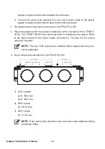
TFM-RT-5/6K (TFM502R4RT2N035) Rear Panel
O
U
TP
U
T
BR
EA
KE
R
-2
25
0V AC 20
A
OUTPUT SOCKET-2
20A MAX.
OUTPUT SOCKET-1
30A MAX.
INPUT BREAKER
250V AC 30A
TRANSFORMER PROTECTION
BREAKER 8A
AC INPUT
O
U
TP
U
T
SO
C
KE
T-
3
2
0A
MA
X.
OUTPUT BREAKER-3
250V AC 20A
O
U
TP
U
T
SO
C
KE
T-
4
20
A MAX
.
OUTPUT BREAKER-4
250V AC 20A
(Rear View)
1
2
3
8
6
7
4
5
9
10
No.
Description
1
Load 1: 208V output receptacle (L6-30R x 1).
2
Load 2: 208V output receptacle (L6-20R x 1).
3
Load 3: 120V output receptacles (5-15/ 20R x 3).
4
Load 4: 120V output receptacles (5-15/ 20R x 3).
5
The Load 2 circuit breaker will trip when the load exceeds the power
rating.
6
The Load 3 circuit breaker will trip when the load exceeds the power
rating.
7
The Load 4 circuit breaker will trip when the load exceeds the power
rating.
8
The input circuit breaker will trip when the load exceeds the TFM-RT’s
power rating.
9
The TFM-RT’s circuit breaker will trip when the TFM-RT becomes
overheated.


