background image

10- ENG

A08184

INSTALLATION

GROUNDING INSTRUCTIONS

RISK OF ELECTRICAL SHOCK.  In the event of a short 
circuit, grounding reduces the risk of shock by providing an 

escape wire for the electric current. This air compressor must be properly 
grounded.
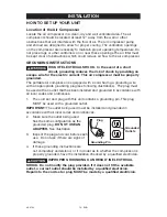
The portable air compressor is equipped with a cord having a grounding wire 
with an appropriate grounding plug (see following illustrations).  The plug must 
be used with an outlet that has been installed and grounded in accordance with 
all local codes and ordinances. 
1.  The cord set and plug with this unit contains a grounding pin. This plug 

MUST be used with a grounded outlet. 

IMPORTANT: The outlet being used must be installed and grounded in 
accordance with all local codes and ordinances. 
2.  Make sure the outlet being used 

has the same configuration as the 
grounded plug. 

DO NOT USE AN 

ADAPTER. See illustration.

3.  Inspect the plug and cord before each 

use.  Do not use if there are signs of 
damage.

4.  If these grounding instructions are 

not completely understood, or if in doubt as to whether the compressor is 
properly grounded, have the installation checked by a qualified electrician.

IMPROPER GROUNDING CAN RESULT IN ELECTRICAL 

SHOCK.


Do not modify the plug provided. If it does not fit the available 

outlet, a correct outlet should be installed by a qualified electrician.
Repairs to the cord set or plug MUST be made by a qualified electrician.

HOW TO SET UP YOUR UNIT

Location of the Air Compressor

Locate the air compressor in a clean, dry and well ventilated area. The air 
compressor should be located at least 12" away from the wall or other 
obstructions that will interfere with the flow of air. The air compressor pump 
and shroud are designed to allow for proper cooling. The ventilation openings 
on the compressor are necessary to maintain proper operating temperature. Do 
not place rags or other containers on or near these openings.The air filter must 
be kept clear of obstructions which could reduce air flow to the air compressor. 

Grounding Pin

Grounded 
Outlets 

Plug

Summary of Contents for 66-651-1

Page 1: ...ght 2004 Delta Machinery To learn more about DELTA MACHINERY visit our website at www deltamachinery com For Parts Service Warranty or other Assistance please call 1 866 422 4286 Oil Free Air Compress...

Page 2: ...the symbols below Please read the manual and pay attention to these symbols IMPORTANT SAFETY INSTRUCTIONS Some dust created by power sanding sawing grinding drilling and other construction activities...

Page 3: ...roperty damage To reduce the risk of fire do not allow the compressor to operate unattended Always operate the compressor in a well ventilated area free of combustible materials gasoline or solvent va...

Page 4: ...ndensed water from tank causing rust and thinning of the steel tank Modifications or attempted repairs to the tank Unauthorized modifications to the unloader valve safety valve or any other components...

Page 5: ...ect voltage and adequate fuse protection Sprayed materials such as paint paint solvents paint remover insecticides weed killers may contain harmful vapors and poisons Work in an area with good cross v...

Page 6: ...thing WARNING Risk of Falling A portable compressor can fall from a table workbench or roof causing damage to the compressor and could result in serious injury or death to the operator Always operate...

Page 7: ...parts WARNING Risk of Unsafe Operation Unsafe operation of your air compressor could lead to serious injury or death to you or others HAZARD WARNING Risk of Serious Injury or Property Damage When Tran...

Page 8: ...starts is called cut in pressure Cut Out Pressure When an air compressor is turned on and begins to run air pressure in the air tank begins to build It builds to a certain high pressure before the mot...

Page 9: ...t be lifted or pushed up a ramp Assemble Rubber Feet 1 Attach rubber feet with the screws provided as shown in previous figure 2 Tighten securely Rubber Feet Screw Nut Wheel Shoulder Bolt ASSEMBLY Too...

Page 10: ...se if there are signs of damage 4 If these grounding instructions are not completely understood or if in doubt as to whether the compressor is properly grounded have the installation checked by a qual...

Page 11: ...and minimum branch circuit requirements Certain air compressors can be operated on a 15 amp circuit if the following conditions are met 1 Voltage supply through branch circuit is 15 amps 2 Circuit is...

Page 12: ...indicates the reserve air pressure in the tank Regulator Controls the air pressure shown on the outlet pressure gauge Turn the knob clockwise to increase pressure and counterclockwise to decrease pre...

Page 13: ...the compressor for 15 minutes Make sure the drain valve is open and there is minimal air pressure build up in tank 6 After 15 minutes close the drain valve clockwise The air receiver will fill to cut...

Page 14: ...NOTE The hose or accessory will require a quick connect plug if the air outlet is equipped with a quick connect Too much air pressure causes a hazardous risk of bursting Check the manufacturer s maxi...

Page 15: ...e type of valve To Drain Tank 1 Set the On Auto Off lever to OFF 2 Turn the regulator knob counterclockwise to set the outlet pressure to zero 3 Remove the air tool or accessory 4 Pull ring on safety...

Page 16: ...o Drain Tank in the Maintenance section 2 Unplug outfit 3 Using an adjustable wrench loosen outlet tube nut at air tank and pump Carefully move outlet tube away from check valve 4 Using an adjustable...
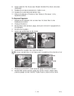
Page 17: ...2 Unplug compressor 3 Remove the outlet pressure gauge and quick connect if equipped from the regulator 4 Remove the regulator 5 Apply pipe sealant tape to the nipple 6 Assemble the regulator and ori...

Page 18: ...roximately 20 psi Release safety valve ring 6 Drain water from air tank by opening drain valve on bottom of tank Water will condense in the air tank If not drained water will corrode and weaken the ai...

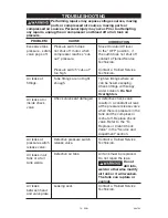
Page 19: ...ttings where air can be heard escaping Check fittings with soapy water solution Do Not Overtighten Air leaks at fittings Air leaks at pressure switch release valve Defective pressure switch release va...

Page 20: ...essor is not supplying enough air to operate accessories Prolonged excessive use of air Compressor is not large enough for air requirement Hole in hose Check valve restricted Air leaks Restricted air...

Page 21: ...ch will automatically reset Tank pressure exceeds pressure switch cut in pressure Motor will start automatically when tank pressure drops below cut in pressure of pressure switch Extension cord is wro...

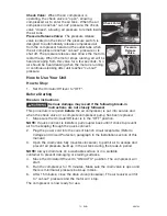
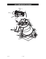
Page 22: ...22 ENG A08184 AIR COMPRESSOR DIAGRAM Torque 5 7 ft lbs 5 24 26 27 28 25 9 10 21 15 17 6 10 11 14 18 4 3 Torque 9 12 ft lbs 2 1 Torque 15 25 ft lbs 32 31 Torque 100 120 in lbs 8 29 30 19 23 22 5 20...

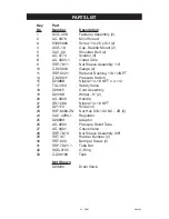
Page 23: ...1 8 1 4NPT 14 Z D26611 Pressure Switch 15 D24888 Nipple 1 4 18 NPT x 2 1 2 17 TIA 4150 Safety Valve 18 D26615 Cord Assembly 19 D23138 Wheel 9 2 20 AC 0609 Handle 21 SS 1286 Nipple 1 4 18 NPT 22 D21172...

Page 24: ...ENG A08184 AIR COMPRESSOR PUMP DIAGRAM Torque 51 63 in lbs Torque 100 120 in lbs Torque 100 120 in lbs Torque 7 10 ft lbs Torque 42 48 in lbs 83 84 85 90 89 87 81 80 91 78 72 70 74 73 76 79 92 93 77...

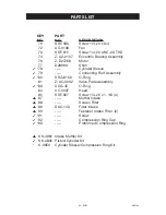
Page 25: ...linder Sleeve 79 Connecting Rod Assembly 80 SSG 8156 O Ring 81 Z AC 0032 Valve Plate Assembly 83 ACG 45 O Ring 84 AC 0037 Head 85 SSF 927 Screw 1 4 20 x 1 1 8 4 87 Muffler Intake 88 Screen Filter 89 D...

Page 26: ...ser Air compressors with 60 and 80 gallon tanks will be inspected at the site of installation Contact the nearest Authorized Warranty Service Center that provides on site service calls for service cal...

Reviews: