Delta 46-755X Instruction Manual Download Page 13

13

LATHE TOOLS

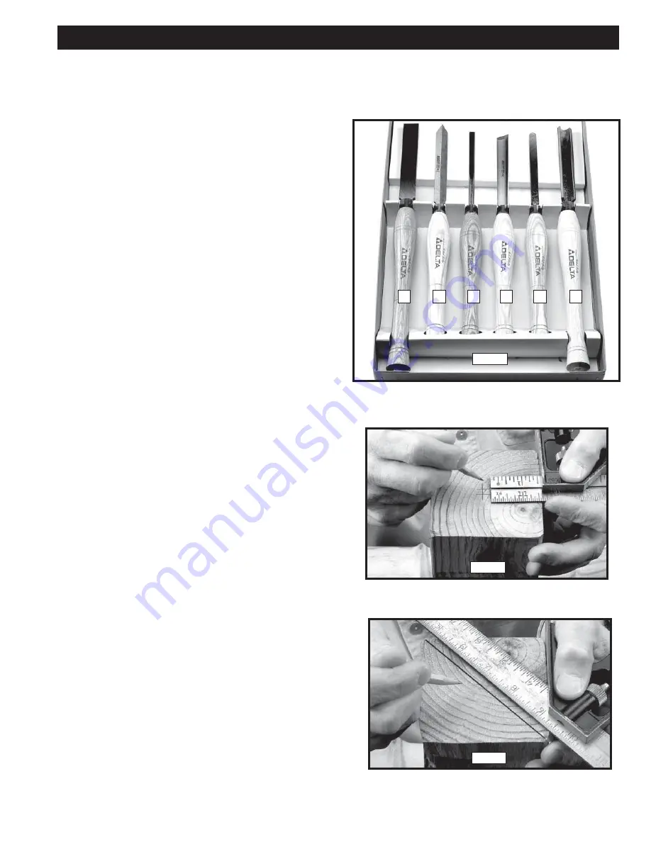
Standard wood turning tools come in several different 
configurations (Fig. 26). The majority of turnings will 
require the gouge tool (A) Fig. 26. This round nosed 


hollow chisel is used for roughing cuts, cove cuts and 
other operations. The skew chisel (B) is a double-ground 
flat chisel, with an angled end. This tool is used for 
smoothing cylinders, for cutting shoulders, beads, vee-
grooves, etc. The parting tool (C) is a double-ground 
chisel, used for cutting-off, or for making straight 


incisions or sizing cuts to any required diameter. The 
round nose scraper (D) is used for mostly hollowing 
work, while the square-end scraper is mainly used for 
the outside of bowls.

The following directions will give the inexperienced operator a beginning point for common lathe operations. Practice 
on scrap material before attempting serious work.

HOW TO TURN SPINDLES

Working with any material that is attached to the lathe 
centers is called a spindle turning. This is the principal 
type of wood turning (chair and table legs, lamp stems, 
etc.) The turning of spindles can be done with either a 
scraping or cutting technique. The cutting technique, by 
virtue of faster wood removal and a cleaner surface, is the 
preferred method. 

CENTERING THE WORK

Wood stock for any spindle turning should be        approx-
imately square, and the ends should be square with the 
sides. Two common methods of determining the center 
are shown in Figs. 27 and 28. In Fig. 27, a  distance a 
little more or a little less than one-half the width of the 
stock is set off from each of the four sides. The small 
square set off in the center can then be used in marking 
the true center. The diagonal method, Fig. 28, consists 
of drawing lines from corner to corner, with the intersec-
tion marking the center of the work.

OPERATION

Fig. 26

Fig. 27

Fig. 28

A

B

D

A

C

E

Summary of Contents for 46-755X

Page 1: ...isit our website at www deltamachinery com For Parts Service Warranty or other Assistance please call 1 800 223 7278 In Canada call 1 800 463 3582 PART NO A16528_02 02 06 Copyright 2006 Delta Machiner...

Page 2: ...machinery com Postal Mail Technical Service Manager Delta Machinery 4825 Highway 45 North Jackson TN 38305 IN CANADA 125 Mural St Suite 300 Richmond Hill ON L4B 1M4 Information regarding the safe and...

Page 3: ...azardous situation which if not avoided may result in property damage SAFETY GUIDELINES DEFINITIONS Some dust created by power sanding sawing grinding drilling and other construction activities contai...

Page 4: ...damage to the machine or injury to the user 14 USE THE PROPER EXTENSION CORD Make sure your extension cord is in good condition When using an extension cord be sure to use one heavy enough to carry th...

Page 5: ...etc before turning the machine ON 14 EXAMINE THE SET UP CAREFULLY before turning the machine ON 15 STAND CLEAR AND KEEP ALL OBSERVERS AND PASSERSBY clear of rotating path of workpiece to avoid injury...

Page 6: ...achine is intended for use on a circuit that has an outlet that looks like the one illustrated in Fig C the machine will have a grounding plug that looks like the plug illustrated in Fig C Make sure t...

Page 7: ...istened with kerosene do not use acetone gasoline or lacquer thinner for this purpose After cleaning cover the top surface of the bed with a good quality paste wax For your own safety do not connect t...

Page 8: ...A Fig 6A between the pedestal A Fig 6B and the pedestal base B Fig 6B NOTE Place the 4 board under the pedestal mark where the holes are located and drill the holes to allow longer carriage bolts not...

Page 9: ...nserting the spur center A clean both the shank of the spur center and the inside of the head stock spindle to remove any grease or debris To remove the tapered shank spur center A Fig 13 from the hea...

Page 10: ...itioned on the left or right side of the tool rest base B To reposition the tool rest locking lever D unscrew the lever counterclockwise A threaded hole is provided in the left side of tool rest base...

Page 11: ...rs the tool rest and to make sure that the spindle lock is in the UNLOCKED position A Fig 21 2 Prior to activating the spindle set the speed control knob A Fig 22 to the zero position Input voltage mu...

Page 12: ...trol is still energized as long as the power switch is on NOTE To lock the spindle or to utilize the indexing fea ture pull the spindle lock pin A Fig 25 out and rotate the pin clockwise Engage it in...

Page 13: ...al before attempting serious work HOW TO TURN SPINDLES Working with any material that is attached to the lathe centers is called a spindle turning This is the principal type of wood turning chair and...

Page 14: ...king each end mark the true center with a punch awl or dividers Fig 29 If the stock is hardwood the centers should be drilled to a depth of about 1 8 The spur or live center is then placed against one...

Page 15: ...in the same direction it is advancing 3 The tool is held well up on the work with the bevel or grind tangent to the revolving surface Fig 35 This position will give a clean shearing cut When pushed st...

Page 16: ...olds the calipers in the cutting groove When parting tool cuts are deep a clearance cut should be made alongside the first cut Fig 40 to prevent burning the tool point SQUARING AN END The parting tool...

Page 17: ...akes this impossible use the skew in a flat scraping position If the cutting technique is used engage only with the heel of skew in a very light cut CUTTING SMALL BEADS Beads can be scraped or cut Usi...

Page 18: ...ng edge is the contact point with the wood As the cut progresses toward and around the end of the curve the handle is gradually raised and swiveled to the right Fig 53 in order to maintain the tangenc...

Page 19: ...at the end of the cut Fig 58 it will be well up on the work and tangent with the cut surface Make only one half of the cut at a time then reverse the chisel to cut the other half The occasional turner...

Page 20: ...TING WORK TO FACEPLATE Fig 63 shows direct mounting to the 4 faceplate along with attaching to the backing block Because of the ease of setting up use this mounting whenever the work permits Hold larg...

Page 21: ...the lathe bed See also Fig 69 4 Lower the handle A Fig 65 to lock the headstock in place 5 Loosen the set screw on the faceplate A Fig 66 two full turns Use the supplied wrench B Fig 67 to loosen the...

Page 22: ...t C Lift the motor A and remove the belt from the motor pulley 4 Pull the motor A Fig 72 out and place it on the lathe bed Fig 73 5 Use a Phillips screwdriver A Fig 74 to remove the five cover screws...

Page 23: ...r this purpose Follow the manufacturer s instructions for use and safety To clean cast iron tables of rust you will need the following materials a sheet of medium Scotch Brite Blending Hand Pad a can...

Page 24: ...ion and repair or replacement Delta will not be responsible for any asserted defect which has resulted from normal wear misuse abuse or repair or alteration made or specifically authorized by anyone o...

Reviews: