Delta 36-R31 Instruction Manual Download Page 18

18

OPERATIONS

Common sawing operations include ripping and crosscutting plus a few other standard operations of a fundamental
nature. As with all power machines, there is a certain amount of hazard involved with the operation and use of the
machine. Using the machine with the respect and caution demanded as far as safety precautions are concerned, will
considerably lessen the possibility of personal injury. However, if normal safety precautions are overlooked or completely
ignored, personal injury to the operator can result. The following information describes the safe and proper method for
performing the most common sawing operations.

THE USE OF ATTACHMENTS AND ACCESSORIES NOT RECOMMENDED BY DELTA MAY RESULT
IN THE RISK OF INJURY TO PERSONS.

CROSS-CUTTING

Cross-cutting requires the use of the miter gage to posi-
tion and guide the work. Place the work against the miter
gage and advance both the gage and work toward the
saw blade, as shown in Fig. 50. The miter gage may be
used in either table slot. When bevel cutting (blade tilted),
use the right miter gage slot so that the blade tilts away
from the miter gage and your hands.
Start the cut slowly and hold the work firmly against the
miter gage and the table. One of the rules in running a
saw is that you never hang onto or touch a free piece of
work. Hold the supported piece, not the free piece that is
cut off. The feed in cross-cutting continues until the work
is cut in two, and the miter gage and work are pulled back
to the starting point. Before pulling the work back, it is
good practice to give the work a little sideways shift to
move the work slightly away from the saw blade. Never
pick up any short length of free work from the table while
the saw is running. Never touch a cutoff piece unless it is
at least a foot long.
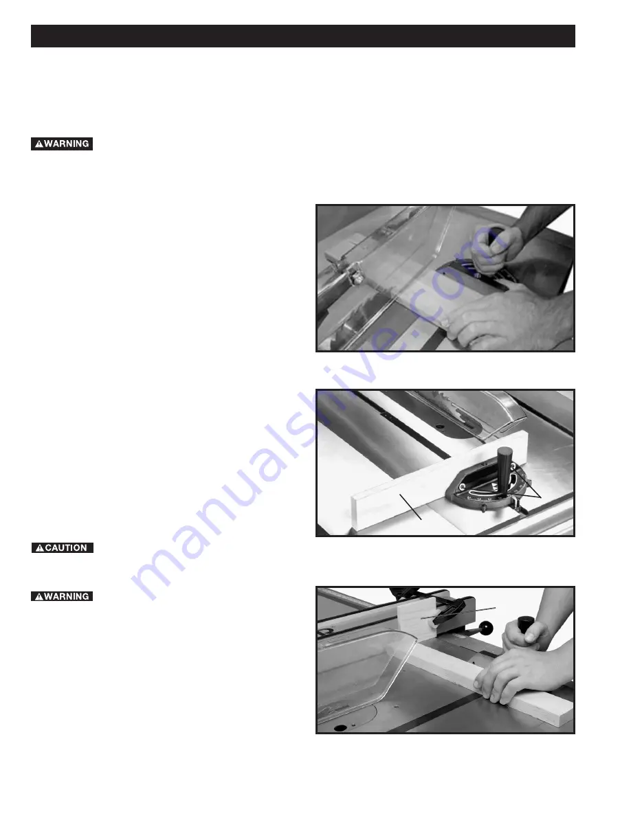
For added safety and convenience the miter gage can be
fitted with an auxiliary wood-facing (C), as shown in Fig.
51, that should be at least 1 inch higher than the
maximum depth of cut, and should extend out 12 inches
or more to one side or the other depending on which
miter gage slot is being used. This auxiliary wood-facing
(C) can be fastened to the front of the miter gage by using
two wood screws (A) through the holes provided in the
miter gage body and into the wood-facing.

When using the block (B) Fig. 52, as a cut-

off gage, it is very important that the rear end of the block
be positioned so the work piece is clear of the block
before it enters the blade.

NEVER USE THE FENCE AS A CUT-OFF

GAGE WHEN CROSS-CUTTING.

When cross-cutting a number of pieces to the same
length, a block of wood (B), can be clamped to the fence
and used as a cut-off gage as shown in Fig. 52. It is
important that this block of wood always be positioned in
front of the saw blade as shown. Once the cut-off length
is determined, secure the fence and use the miter gage to
feed the work into the cut.
This block of wood allows the cut-off piece to move freely
along the table surface without binding between the
fence and the saw blade, thereby lessening the possibility
of kickback and injury to the operator.

Fig. 50

Fig. 51

Fig. 52

C

A

B

Summary of Contents for 36-R31

Page 1: ...36 L53 36 L31X 36 L51X PART NO 422 40 651 0017 05 16 03 Copyright 2003 Delta Machinery To learn more about DELTA MACHINERY visit our website at www deltamachinery com For Parts Service Warranty or ot...

Page 2: ...UNDERSTAND ALL WARNINGS AND OPERATING INSTRUCTIONS BEFORE USING THIS EQUIPMENT Failure to follow all instructions listed below may result in electric shock fire and or serious personal injury or prop...

Page 3: ...HE RIGHT MACHINE Don t force a machine or an attachment to do a job for which it was not designed Damage to the machine and or injury may result 13 USE RECOMMENDED ACCESSORIES The use of accessories a...

Page 4: ...op remove all debris 8 NEVER START THE MACHINE with the workpiece against the blade 9 HOLD THE WORKPIECE FIRMLY against the miter gauge or fence 10 NEVER run the workpiece between the fence and a moul...

Page 5: ...achine should be connected to a grounded metal permanent wiring system or to a system having an equipment grounding conductor 1 All grounded cord connected machines In the event of a malfunction or br...

Page 6: ...IPTION FIVE HORSEPOWER MOTORS The motors supplied with single phase 5 horsepower Unisaws are designed to be operated from a 220 240 volt power system The 5 horsepower Unisaws are not supplied with a p...

Page 7: ...90 degree position and remove the styrofoam packing from inside the saw cabinet Tighten locking knob UNISAW PARTS 3 4 5 6 7 8 9 10 11 12 13 14 15 16 17 18 19 20 21 22 23 24 25 26 27 28 29 31 32 33 34...

Page 8: ...h an GPE starter box the GPE ON OFF switch must be removed from the left side of the Unisaw When assembling the left extension wing do not install the front screw and washer at this time it will be in...

Page 9: ...1 4 20 x 1 2 hex head screw into the hole B Fig 7 in the cabinet Repeat this process for the two remaining screws 2 Line up the three tapped holes C Fig 7 in the starter box with the screws and secure...

Page 10: ...HINE FROM POWER SOURCE 1 Remove the table insert Fig 14 Raise the saw arbor by turning the locking handle on the front of the saw counter clockwise and then turn the wheel on the front of the saw cloc...

Page 11: ...possible by hand 6 Using a wrench to hold the 5 8 18 hex jam nut J Fig 19 tighten rod G Fig 20 with a small screwdriver K or similar device through the hole in the end of the rod as shown in Figure 20...

Page 12: ...tter This notch enables the blade guard to stay in the raised position and makes changing blades easier 11 Reassemble the saw blade making certain the teeth are pointing down at the front of the saw t...

Page 13: ...ig 33 A MOTOR COVER NOTE IF YOU HAVE AN LVC STARTER BOX VERSION UNISAW YOU WILL HAVE TO ATTACH TWO BOTTOM SPRING CLIPS TO THE MOTOR COVER IF YOU HAVE AN GPE STARTER BOX VERSION UNISAW THE SPRING CLIPS...

Page 14: ...D SCREW B FIG 35 AND PUSH MOTOR COVER TO ONE SIDE TO DEPRESS CLIPS AND PULL MOTOR COVER OFF Fig 34 Fig 35 RIP FENCE HOLDER BRACKETS Assemble the rip fence holder brackets A and B Fig 36 to the four ho...

Page 15: ...blade raising mechanism securely Any added force merely puts unnecessary strain on the locking device Limit stops for raising or lowering are permanently built into the mechanism and need no further a...

Page 16: ...shown Loosen locknut C and tighten or loosen adjusting screw D until head of screw D contacts casting on front trunnion when the blade is at 45 degrees to the table Then tighten locknut C Fig 42 Fig...

Page 17: ...out of the way and move the body of the miter gage C to the desired angle The miter gage body C can stop at 90 degrees and 45 degrees both right and left by flipping the stop link down and out of the...

Page 18: ...r gage and work are pulled back to the starting point Before pulling the work back it is good practice to give the work a little sideways shift to move the work slightly away from the saw blade Never...

Page 19: ...ork rides against the rip fence while the flat side of the board rests on the table Since the work is pushed along the fence it must have a straight edge and make solid contact with the table The saw...

Page 20: ...used when ripping thin material such as paneling to prevent the material from catching between the bottom of the rip fence and the saw table surface USING ACCESSORY MOULDING CUTTERHEAD Moulding is cu...

Page 21: ...s necessary when using the moulding cutterhead to add wood facing C to the face of the rip fence as shown in Fig 65 The wood facing is attached to the Biesemeyer fence with two clamps as shown refer t...

Page 22: ...idth of groove A 1 4 groove is cut by using the two outside saws The teeth of the saws should be positioned so that the raker on one saw is beside the cutting teeth on the other saw The dado head set...

Page 23: ...g the saw blade a box end wrench and open end wrench 2 Remove table insert and raise saw blade to its maximum height 3 Place the open end wrench B Fig 73 on the flats of the saw arbor to keep the arbo...

Page 24: ...ey F 7 Assemble the three new belts one at a time in the grooves of the arbor pulley F Fig 75 and onto the motor pulley 8 When the new belts are assembled on the arbor pulley F Fig 75 and the motor pu...

Page 25: ...o keep the work in contact with the fence and table and help prevent kickbacks Clamp the featherboards to the fence and table so that the leading edge of the featherboards will support the workpiece u...

Page 26: ...ERE TO PUSH 1 4 WOOD CUT OFF HERE TO PUSH 1 2 WOOD NOTCH TO HELP PREVENT HAND FROM SLIPPING 1 2 SQUARES CONSTRUCTING A PUSH STICK When ripping work less than 4 inches wide a push stick should be used...

Page 27: ...PACITY BIESEMEYER COMMERCIAL 30 CAPACITY BIESEMEYER COMMERCIAL 50 CAPACITY Two Year Limited New Product Warranty Delta will repair or replace at its expense and at its option any new Delta machine mac...

Page 28: ...ern Avenue Suite 105 Phone 602 437 1200 Fax 602 437 2200 CALIFORNIA Ontario 91761 Los Angeles 3949A East Guasti Road Phone 909 390 5555 Fax 909 390 5554 San Leandro 94577 Oakland 3039 Teagarden Street...

Reviews: