Delta 33-830 Instruction Manual Download Page 17

17

Fig. 41

Fig. 42

Fig. 43

5.

Place a square (D) Fig. 41, on the table and against

the saw blade, as shown, and check to see if the blade
is square with the table. 

NOTE: The square should rest

between two teeth of the saw blade

.

6.

If an adjustment is necessary, make certain bevel

clamp lever (C) Fig. 40, is tight. Remove screw, flat
washer, and pointer (E) Fig. 40. Remove two screws (F)
Fig. 40, and bevel scale plate (H) Fig. 42, with index
knob (A).

7.

Loosen four hex head screws (G) Fig. 42. Tilt the

motor until the saw blade is flush with the square.
Tighten four hex head screws (G).

8.

Replace bevel scale plate (H) Fig. 42, with bevel

index release knob (A), two screws, and pointer that
were removed in

STEP 6

NOTE: Adjust pointer to

“zero” on the bevel index scale.
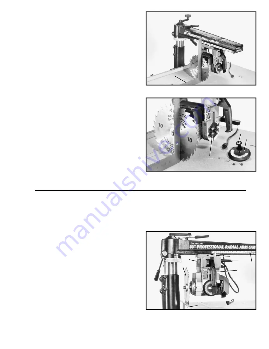
1.

DISCONNECT TOOL FROM POWER SOURCE

.

2. Loosen yoke clamp handle (A) Fig. 43. Release yoke
index by pressing yoke indexing release lever (B) up or
down, and rotating cutting-head (C) to the in-rip
position as shown. Tighten yoke clamp lever (A).

3.

Position fence (D) Fig. 43, at the rear of table as

shown.

4.

Loosen cutting-head clamp knob (G) Fig. 48 and

slide cutting-head (C) Fig. 43, to rear of track arm until
saw blade (F) is flush against fence (D).

5.

Tighten cutting-head clamp knob (G) Fig. 48 and

adjust pointer (H) Fig. 43, if necessary, to “zero” mark on
lower scale (J) by loosening screw (K). After adjustment
is made, tighten screw (K).

D

G

A

H

A

J

K

C

D

F

B

H

ADJUSTING IN/OUT RIP SCALE

Summary of Contents for 33-830

Page 1: ...PART NO 424 12 651 0031 019 Copyright 2001 Delta Machinery ESPA OL P GINA 29 To learn more about DELTA MACHINERY visit our website at www deltamachinery com For Parts Service Warranty or other Assist...

Page 2: ...y to get caught in moving parts Nonslip footwear is recommended Wear protective hair covering to contain long hair 12 SECURE WORK Use clamps or a vise to hold work when practical It s safer than using...

Page 3: ...irs 28 TURN THE TOOL OFF disconnect the tool from the power source and clean the table work area before leaving the tool 29 NEVER leave the work area when the power is ON or before the tool has come t...

Page 4: ...ermitted by the Canadian Electric Code 3 Grounded cord connected tools intended for use on a supply circuit having a nominal rating between 150 250 volts inclusive If the tool is intended for use on a...

Page 5: ...ry to replace the 120 volt plug supplied with the motor with a UL CSA listed plug suitable for 240 volts and the rated current of the saw Contact your local Authorized Delta Service Center or qualifie...

Page 6: ...ted surfaces with a good quality household floor paste wax NOTICE THE MANUAL COVER PHOTO ILLUSTRATES THE CURRENT PRODUCTION MODEL ALL OTHER ILLUSTRATIONS ARE REPRESENTATIVE ONLY AND MAY NOT DEPICT THE...

Page 7: ...ard 9 Rear Table Board 10 Middle Table Board 11 Fence Board 12 1 4 20 Flange Nuts 4 13 1 4 20 x 1 Truss Head Screws 4 14 Wrenches 15 1 4 20 x 1 1 4 Pan Head Screws 4 16 5 16 18 x 5 8 Carriage Head Scr...

Page 8: ...tion of the yoke for ripping or cross cutting operations When rotating the yoke the yoke clamp handle must first be loose Push the release lever either up or down to release the indexing pin Fig 6 L Y...

Page 9: ...mped securely at the back of the track arm 3 Place Radial Arm Saw on its back and assemble legs C Fig 9 three of which are shown assembled to each corner of saw base D using sixteen 5 16 18 x 5 8 carr...

Page 10: ...shown 3 With wrenches supplied C Fig 12 loosen arbor nut D as much as possible NOTE Arbor nut has left hand threads 4 Lift cam E Fig 13 which holds the blade guard B Fig 12 in position and move the b...

Page 11: ...orts B Secure in place using four flanged hex nuts E Do not completely tighten nuts at this time 3 Place front table board A Fig 17 onto saw base G so that table supports B straddle the outside of saw...

Page 12: ...igs 21 and 22 into holes R Fig 21 of table board as shown and tighten each of the screws until each corner of the table board raises approximately 1 8 8 Loosen bevel clamp lever S Fig 23 pull out beve...

Page 13: ...tting head assembly V until the highest point of the table is determined NOTE MAKE CERTAIN CUTTING HEAD CLAMP KNOB W FIG 27 AND TRACK ARM CLAMP HANDLE Y ARE TIGHTENED WHEN MOTOR SHAFT IS LOCATED ABOVE...

Page 14: ...wide board J against 1 3 4 wide board as shown Then tighten knobs D until the table boards are securely clamped in position ADJUSTING AND CHECKING SAW BLADE TRAVEL SQUARE TO FENCE 1 DISCONNECT TOOL F...

Page 15: ...travels parallel to square E Then tighten track arm clamp handle K Fig 34 8 With track arm clamp handle K Fig 35 tightened rotate index ring L counterclockwise until it stops Then tighten index ring...

Page 16: ...the teeth of the blade 5 If the blade is not parallel to the square an adjustment is necessary Release the yoke clamp handle C Fig 39 and slightly loosen two hex head screws D Swivel the yoke until th...

Page 17: ...ith bevel index release knob A two screws and pointer that were removed in STEP 6 NOTE Adjust pointer to zero on the bevel index scale 1 DISCONNECT TOOL FROM POWER SOURCE 2 Loosen yoke clamp handle A...

Page 18: ...or nut E using two wrenches G supplied 7 Rotate blade guard B Fig 46 to the horizontal position and tighten clamp knob H IMPORTANT CLAMP KNOB H FIG 46 MUST BE TIGHT AND BLADE GUARD SECURE DURING OPERA...

Page 19: ...g head handle L Fig 49 firmly turn switch H ON and lower track arm E by turning elevating handle K as shown Lower saw blade until it cuts into the table surface approximately 1 16 deep Then stop turni...

Page 20: ...ig 63 through hole G in track arm slightly loosen hex nut on adjustable shaft B Fig 61 approximately 1 8 turn Repeat procedure for other bearing E D G H G C Fig 61 B B A C K Fig 56 ON OFF SWITCH The o...

Page 21: ...ustment to column base B Fig 65 is made by loosening hex nuts D and turning screws E until column base wraps around column securely and can be raised or lowered without binding Then tighten hex nuts D...

Page 22: ...clamp lever A while holding in on hex bolt B When the clamp lever A comes off hex bolt B rotate clamp lever A 180 degrees Then start to tighten clamp lever A CHANGING POSITION OF BEVEL CLAMP HANDLE W...

Page 23: ...l scale C and tighten bevel clamp handle B Fig 72 ADJUSTING SPLITTER AND ANTI KICKBACK FINGERS During ripping operations the splitter A Fig 73 must ride in the saw kerf and the anti kickback fingers B...

Page 24: ...st the fence and pulling the saw blade through the material at right angles to it When cross cutting the track arm should be indexed at 0 and the track arm clamp handle tightened The fence should be c...

Page 25: ...JUSTING SPLITTER AND ANTI KICKBACK FINGERS in this manual The operators hands should always be well away from and to the side of the blade When ripping narrow work always use a push stick as shown in...

Page 26: ...plete the feed and could easily be made from scrap material by following the pattern shown in Fig 79 Fig 79 PUSH STICK MAKE FROM 1 2 OR 3 4 WOOD OR THICKNESS LESS THAN WIDTH OF MAT L TO BE CUT CUT OFF...

Page 27: ...will repair or replace at its expense and at its option any Delta machine machine part or machine accessory which in normal use has proven to be defective in workmanship or material provided that the...

Page 28: ...28 NOTES...

Page 29: ...rio 91761 Los Angeles 3949A East Guasti Road Phone 909 390 5555 Fax 909 390 5554 San Leandro 94577 Oakland 3039 Teagarden Street Phone 510 357 9762 Fax 510 357 7939 FLORIDA Davie 33314 Miami 4343 Sout...

Reviews: