


The lower bearing adjustments are similar to the upper bearing
adjustments. Adjust the blade support bearing (A) Fig 23 so that
it is within 1/64” of, but not touching the back of the saw blade
when the blade is at rest. To adjust, loosen hex screw (B) and slide
the bracket in or out until the adjustment is correct. Tighten the
screw. Adjust the blade guide bearings (C,G) by loosening the
screw (E) and rotating the bearing on the shaft (F) so that the
bearings touch, but do not pinch the blade. To gain access the
back bearing (G), you will need to remove the table insert and tilt
the table to the right. Return table to level position. The front edge
of the guide bearings (C) should be just behind the “gullets” of the
saw teeth. To adjust, loosen the hex screw (D) and slide the bearing assembly into place. Tighten the hex screw (D).
14
Fig. 21
ADJUSTING UPPER BLADE GUIDE ASSEMBLY
Set the upper blade guide assembly (A) Fig. 21 as close as possible to the top surface of the workpiece by loosening the lock
knob (D) and turning the handle (B) until the guide assembly is in the correct position. A scale (C) Fig. 21 in increments of 1/8"
is located above the assembly.
ADJUSTING UPPER BLADE GUIDE AND BLADE SUPPORT BEARING
Adjust the blade support bearing (B) Fig. 22 so that it is within 1/64” of, but not touching the back of the saw blade when the
blade is at rest. To adjust, loosen the indexable locking lever (C) and slide the bracket in or out until the adjustment is correct.
Tighten the lever (C). Adjust the blade guide bearings (D) by loosening the screw (F) and rotating the bearing on the shaft (G)
so that the bearings touch, but do not pinch the blade. Tighten the screw (F).Position the front edge of the guide bearings just
behind the “gullets” of the saw teeth. To adjust, loosen indexable locking lever (E) and slide the bearing assembly in or out
until the adjustment is correct. Tighten the lever.
Fig. 22
Fig. 23
ADJUSTING LOWER BLADE GUIDE AND BLADE SUPPORT BEARING
DISCONNECT MACHINE FROM POWER
SOURCE.
A
B
D
C
DISCONNECT MACHINE FROM POWER SOURCE.
A
B
C
D
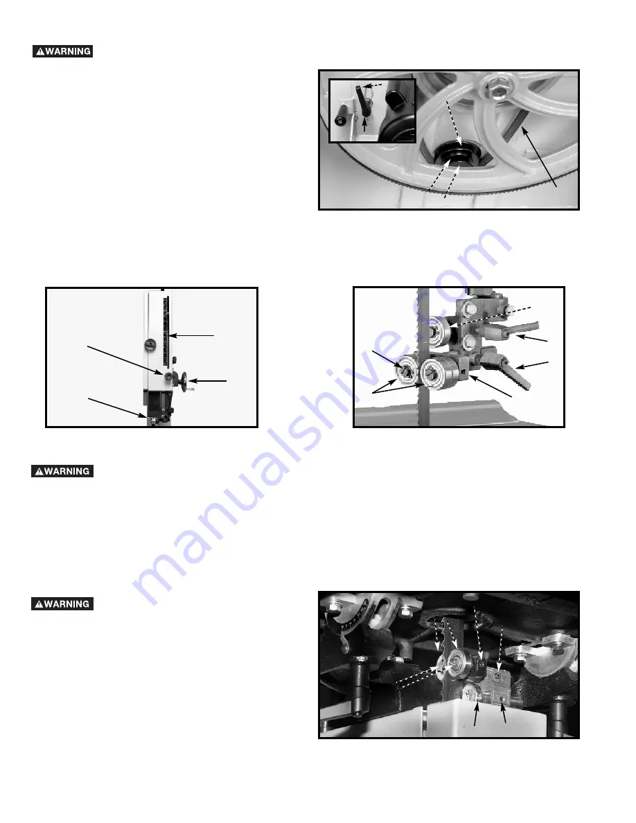
CHANGING SPEEDS
DISCONNECT MACHINE FROM POWER SOURCE.
1.
Open the bottom access door (See D, Fig. 26).
2.
Locate and loosen motor release handle (C) Fig. 20A
inset by turning it counter-clockwise.
3.
Lift up motor assembly and move belt (A) to desired
groove on motor pulley (B). Move belt to outer groove
(D) for 2300 SFPM, or to inner groove (E) for 3250
SFPM.
4.
Push down on motor assembly and then turn motor
release handle (C) clockwise to tighten belt.
5.
Close the bottom access door.
Fig. 20A
A
B
C
B
C
D
G
F
E
E
D
E
F
G