


6
ATTACHING BELT GUARD, MOTOR AND ARBOR PULLEYS,
AND DRIVE BELT
1. Thread the six #10-32 x 5/8" self-tapping screws (A) Fig. 9 about halfway into the six holes provided in the ledge of the inside
belt and pulley guard (B).
2. Place the inside belt and pulley guard (B) Fig. 10 over the arbor shaft (C) and motor shaft (D), and fasten the guard (B) to the
tool using the two 1/2" hex head cap screws and flat washers (A).
NOTE:
Partially tighten the screws at this point.
3. Place the spacer (E) Fig. 11 against the countersunk hole (F) located behind the belt and pulley guard (B). Insert the 5/16-
18 x 2 3/4" hex head cap screw with a flat washer (G) into the center hole (H), through the spacer (E). Attach a lock washer and
thread it into the countersunk hole (F).
4.
NOTE:
Center the arbor shaft (C) Fig. 12 and the motor shaft (D) in the holes of the belt and pulley guard (B). Tighten the
screws (J) and (K).
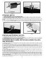
5. Attach the arbor pulley (L) Fig. 13 to the arbor shaft (C) with the hub of the pulley in the “out” position. Insert key (M) in key-
way of arbor shaft. Tighten the set screw (N).
6. Attach the motor pulley (O) Fig. 14 to the motor shaft (B) with the hub of the pulley in the “in” position. Insert the key (P) in
the keyway of the motor shaft. Tighten the set screw (R) in motor pulley.
7. Attach the drive belt (S) Fig. 15 to the arbor pulley (L) and motor pulley (O). Use a straight edge to see if the arbor pulley (L)
and the motor pulley (O) are aligned. Either pulley can be moved to create proper alignment by loosening the set screw. To adjust
belt tension, loosen the four mounting bolts (T) (two of which are shown). Move the motor in or out until belt deflection is approx-
imately 1/2" using light finger pressure.
NOTE:
After getting the correct tension on the belt and after aligning the pulleys,
tight-
en all mounting hardware
.
8. Attach the outer belt and pulley guard (V) Fig. 16 to the inside belt and pulley guard (B) Fig. 12. Tighten the six screws, three
of which are shown at (W) Fig. 16.
6
STARTING AND STOPPING THE TOOL
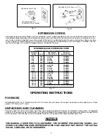
1. To start the motor, lift the switch (A) Fig. 7 to the “up” position.
2. To stop the motor, push the switch (A) Fig. 7 to the “down” position.
3.
IMPORTANT: When the tool is not in use, the switch should be locked in the “OFF” position to prevent unauthorized
use, using a padlock (A) Fig. 8 with a 3/16" diameter shackle.
Fig. 5
Fig. 6
Fig. 7
Fig. 8
ATTACHING SWITCH
1.
CAUTION: DISCONNECT TOOL FROM POWER SOURCE.
2
. CAUTION: Follow this procedure to ensure proper grounding of the switch to prevent an electric shock hazard.
3. Remove the outer hex nut (A) Fig. 5 from the switch (B).
4. Insert the switch through the hole in the side of the top shelf of the stand. Place the switch (C) Fig. 6 in the down or “off”
position.
5. Place the switch bracket (D) Fig. 6 on the switch with the key of switch bracket engaged with the keyway. Fasten switch
with hex nut (A) (removed in
STEP 2
).
NOTE:
Tie the excess wire from the motor to the switch and position it out of the way.
D
A
A
A
A
B
C