background image

2

GENERAL SAFETY RULES

Woodworking can be dangerous if safe and proper operating procedures are not followed. As with all machinery, there
are certain hazards involved with the operation of the product. Using the machine with respect and caution will
considerably lessen the possibility of personal injury. However, if normal safety precautions are overlooked or ignored,
personal injury to the operator may result. Safety equipment such as guards, push sticks, hold-downs, featherboards,
goggles, dust masks and hearing protection can reduce your potential for injury. But even the best guard won’t make up
for poor judgment, carelessness or inattention. Always use common sense and exercise caution in the workshop. If a
procedure feels dangerous, don’t try it. Figure out an alternative procedure that feels safer. REMEMBER: Your
personal safety is your responsibility.

This machine was designed for certain applications only. Delta Machinery strongly recommends that this machine not
be modified and/or used for any application other than that for which it was designed. If you have any questions relative
to a particular application, DO NOT use the machine until you have first contacted Delta to determine if it can or should
be performed on the product.

Technical Service Manager
Delta Machinery
4825 Highway 45 North
Jackson, TN 38305

(IN CANADA: 505 SOUTHGATE DRIVE, GUELPH, ONTARIO  N1H 6M7)

WARNING:

Read and understand all instructions. Failure to follow all instructions listed below may result in 

electric shock, fire and/or serious injury.

1. FOR YOUR OWN SAFETY, READ INSTRUCTION

MANUAL BEFORE OPERATING THE TOOL. Learn the
tool’s application and limitations as well as the specific
hazards peculiar to it.

2. KEEP GUARDS IN PLACE and in working order.
3. ALWAYS WEAR EYE PROTECTION. Wear safety

glasses. Everyday eyeglasses only have impact resistant
lenses; they are not safety glasses. Also use face or dust
mask if cutting operation is dusty. These safety glasses
must conform to ANSI Z87.1 requirements. NOTE:
Approved glasses have Z87 printed or stamped on them.

4. REMOVE ADJUSTING KEYS AND WRENCHES. Form

habit of checking to see that keys and adjusting wrenches
are removed from tool before turning it “on”.

5. KEEP WORK AREA CLEAN. Cluttered areas and

benches invite accidents.

6. DON’T USE IN DANGEROUS ENVIRONMENT.  Don’t

use power tools in damp or wet locations, or expose them to
rain. Keep work area well-lighted.

7. KEEP CHILDREN AND VISITORS AWAY. All children

and visitors should be kept a safe distance from work area.

8. MAKE WORKSHOP CHILDPROOF – with padlocks,

master switches, or by removing starter keys.

9. DON’T FORCE TOOL. It will do the job better and be

safer at the rate for which it was designed.
10. USE RIGHT TOOL. Don’t force tool or attachment to do
a job for which it was not designed.
11. WEAR PROPER APPAREL. No loose clothing, gloves,
neckties, rings, bracelets, or other jewelry to get caught in
moving parts. Nonslip footwear is recommended. Wear
protective hair covering to contain long hair.
12. SECURE WORK. Use clamps or a vise to hold work
when practical. It’s safer than using your hand and frees
both hands to operate tool.
13. DON’T OVERREACH. Keep proper footing and
balance at all times.
14. MAINTAIN TOOLS IN TOP CONDITION. Keep tools
sharp and clean for best and safest performance. Follow
instructions for lubricating and changing accessories.
15. DISCONNECT TOOLS before servicing and when
changing accessories such as blades, bits, cutters, etc.
16. USE RECOMMENDED ACCESSORIES. The use of
accessories and attachments not recommended by Delta
may cause hazards or risk of injury to persons.
17. REDUCE THE RISK OF UNINTENTIONAL STARTING.
Make sure switch is in “OFF” position before plugging in

power cord. In the event of a power failure, move switch to
the “OFF” position.
18. NEVER STAND ON TOOL. Serious injury could occur if
the tool is tipped or if the cutting tool is accidentally
contacted.
19. CHECK DAMAGED PARTS. Before further use of the
tool, a guard or other part that is damaged should be
carefully checked to ensure that it will operate properly and
perform its intended function – check for alignment of
moving parts, binding of moving parts, breakage of parts,
mounting, and any other conditions that may affect its
operation. A guard or other part that is damaged should be
properly repaired or replaced.
20. DIRECTION OF FEED. Feed work into a blade or cutter
against the direction of rotation of the blade or cutter only.
21. NEVER LEAVE TOOL RUNNING UNATTENDED.
TURN POWER OFF
. Don’t leave tool until it comes to a
complete stop.
22.

STAY ALERT, WATCH WHAT YOU ARE DOING, AND

USE COMMON SENSE WHEN OPERATING A POWER
TOOL. DO NOT USE TOOL WHILE TIRED OR UNDER
THE INFLUENCE OF DRUGS, ALCOHOL, OR
MEDICATION. 
A moment of inattention while operating
power tools may result in serious personal injury.

23. MAKE SURE TOOL IS DISCONNECTED FROM
POWER SUPPLY 
while motor is being mounted, connected
or reconnected.
24. THE DUST GENERATED by certain woods and wood
products can be injurious to your health. Always operate
machinery in well ventilated areas and provide for proper
dust removal. Use wood dust collection systems whenever
possible.

25. 

WARNING: SOME DUST CREATED BY

POWER SANDING, SAWING, GRINDING, DRILLING,
AND OTHER CONSTRUCTION ACTIVITIES 
contains
chemicals known to cause cancer, birth defects or other
reproductive harm. Some examples of these chemicals
are:
·  lead from lead-based paints,
· crystalline silica from bricks and cement and other

masonry products, and

·  arsenic and chromium from chemically-treated lumber. 
Your risk from these exposures varies, depending on how
often you do this type of work. To reduce your exposure to
these chemicals: work in a well ventilated area, and work
with approved safety equipment, such as those dust
masks that are specially designed to filter out microscopic
particles.

SAVE THESE INSTRUCTIONS. 

Refer to them often and use them to instruct others. 

Summary of Contents for 16 SM600

Page 1: ... Model SM600 PART NO 638519 00 10 30 05 Copyright 2005 Delta Machinery ESPA OL P GINA 21 To learn more about DELTA MACHINERY visit our website at www deltamachinery com For Parts Service Warranty or other Assistance please call 1 800 223 7278 In Canada call 1 800 463 3582 FRAN AIS PAGE 41 ...

Page 2: ...ckties rings bracelets or other jewelry to get caught in moving parts Nonslip footwear is recommended Wear protective hair covering to contain long hair 12 SECURE WORK Use clamps or a vise to hold work when practical It s safer than using your hand and frees both hands to operate tool 13 DON T OVERREACH Keep proper footing and balance at all times 14 MAINTAIN TOOLS IN TOP CONDITION Keep tools shar...

Page 3: ...of attachments and accessories not recommended by Delta may result in the risk of injuries 19 ALWAYS hold the work firmly against the table 20 DO NOT feed the material too fast while cutting Only feed the material fast enough so that the blade will cut 21 NEVER start the Scroll Saw with the stock pressed against the blade 22 WHEN cutting a large workpiece MAKE SURE the material is supported at tab...

Page 4: ...r should be used only until a properly grounded outlet can be installed by a qualified electrician The green colored rigid ear lug and the like extending from the adapter must be connected to a permanent ground such as a properly grounded outlet box Whenever the adapter is used it must be held in place with a metal screw NOTE In Canada the use of a temporary adapter is not permitted by the Canadia...

Page 5: ...ems from the shipping container s Remove the protective coating from all unpainted surfaces This coating may be removed with a soft cloth moistened with kerosene do not use acetone gasoline or lacquer thinner for this purpose After cleaning cover the unpainted surfaces with a good quality household floor paste wax NOTICE THE MANUAL COVER PHOTO ILLUSTRATES THE CURRENT PRODUCTION MODEL ALL OTHER ILL...

Page 6: ...ll Saw with blade attached 1 Fig 2 2 Table 3 Quickset Blade Changing Wrench 4 Holddown Rod 5 4mm Hex Wrench 6 Locking Handle 7 M10 Flat Washer 8 Blank Table Insert 9 Table Insert 10 Special Screw M6x1x45mm 2 11 M6 Locknut 2 2 3 4 5 6 7 8 9 10 11 ...

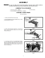
Page 7: ...ower blade holder This will align wrench H with blade holder screw J Turn wrench H counter clockwise This will release the blade from the lower chuck assembly Fig 3 A Fig 4 B C D Fig 5 F G H J ASSEMBLY TOOLS REQUIRED ASSEMBLY TIME ESTIMATE 1 4mm hex wrench supplied 2 Quickset Blade Changing Wrench supplied 3 10mm wrench Less than one hour For your own safety do not connect the machine to the power...

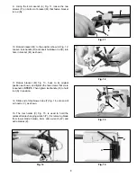
Page 8: ... table A to the base P using the two M6x1x45mm special screws B and M6 locknuts C as shown 6 Disassemble the handle by unscrewing and remov ing screw and spring F and handle G from locking stud H as shown in Fig 8 Place a M10 flat washer J on threaded end of stud H 7 Screw threaded end of stud H Fig 9 with the M10 flat washer J through slot in angle of tilt scale D and into tapped hole K 8 Place h...

Page 9: ... 11 Rotate bracket M Fig 13 back to its original position as shown and tighten the two screws that were loosened in STEP 9 Then tighten lockhandle R to hold rod S in position Fig 13 M N S R 12 Slide end of chip blower tube T Fig 14 onto end of air nozzle V as shown Fig 14 T V Fig 15 13 The tool holder X Fig 15 is used to hold the quickset blade changing wrench Y for removing blade from lower blade...

Page 10: ...CHES The on off switch A Fig 17 and variable speed switch B is located on the right side of the scroll saw base as shown To turn the saw ON push the switch A up to the ON position To turn the saw OFF push the switch A down to the OFF position The scroll saw is equipped with a variable speed control knob B Fig 17 The variable speed range is 400 to 1800 strokes per minute When the variable speed kno...

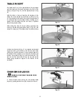
Page 11: ...el cutting operations the insert A should be positioned as shown in Fig 20 This allows for clearance of the blade when the table is tilting Fig 19 Fig 20 A A Fig 21 A B A table insert blank B Fig 21 is supplied as standard equipment with your scroll saw and can be used when cutting very small workpieces to give added support to the bottom of the workpiece Cut a slot into the blank and replace the ...

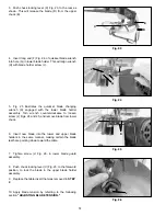
Page 12: ...ssembly Turn wrench counterclockwise to loosen screw J Figs 24 and 25 and remove blade from lower chuck 6 Insert new blade into the lower and upper blade holders in the same manner making certain the blade teeth are pointing down toward the table 7 Tighten screw J Fig 26 in lower blade guard assembly 8 Push chuck locking lever C Fig 23 to the foreword position to lock the blade in the upper blade ...

Page 13: ...side cutting operations Adjusting the blade for proper tension is usually accomplished by trial and error One method is to pull back on the blade tension lever A Fig 28 the blade should start to have tension resistance when the blade tension lever is half way between open Fig 28 and closed Fig 27 Finer blades require more tensioning while thicker blades require less tension Fig 27 Fig 28 A A B ADJ...

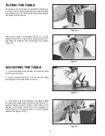
Page 14: ...the holddown B accordingly Then tighten screw C A ADJUSTING THE TABLE Fig 32 Fig 33 1 Loosen the table locking handle and move the table all the way to the right 2 Using a square A Fig 32 check to see if the table is 90 degrees to the saw blade as shown 3 If the table is not at 90 degrees to the blade adjust the table accordingly making certain screw B Fig 33 contacts bottom of table surface when ...

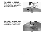
Page 15: ...k being cut by loosening lock handle B and moving holddown rod C up or down Then tighten lock handle B ADJUSTING DUST BLOWER The dust blower A Fig 35 may be moved to direct air to the most effective point on the cutting line by loosening screw B adjust nozzle A and tighten screw B Fig 34 A B C Fig 35 B A ...

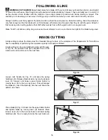
Page 16: ...er spring holddown B You are ready to make the next inside cut FOLLOWING A LINE WARNING CUT HAZARD Keep hands away from blade With your scroll saw you should be able to cut a straight or curved line with ease Most beginners will experience blade wandering however they eventually learn to control it as they become more familiar with the machine Use scrap material to practice cuts before starting a ...

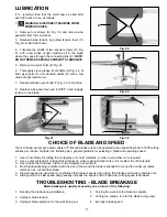
Page 17: ... 4 Forcing the work into the blade too rapidly 5 Cutting too sharp a turn for the blade being used 6 Improper blade speed It is recommended that the scroll saw be oiled after each 20 hours of use as follows CHOICE OF BLADE AND SPEED Your scroll saw will accept a wide variety of 5 flat end blades and can be operated at any speed from 400 to 1800 cutting strokes per minute Consider the following as ...

Page 18: ...18 NOTES ...

Page 19: ...19 NOTES ...

Page 20: ...a s sole warranty and sets forth the customer s exclusive remedy with respect to defective products all other warranties express or implied whether of merchantability fitness for purpose or otherwise are expressly disclaimed by Delta Printed in China PARTS SERVICE OR WARRANTY ASSISTANCE All Delta Machines and accessories are manufactured to high quality standards and are serviced by a network of P...

Page 21: ...achinery com Para las piezas el servicio la garant a o la otra ayuda llaman por favor 1 800 223 7278 en la llamada 1 800 463 3582 de Canada MANUAL DE INSTRUCCIONES Sierra de Calar de 16 pulg de Velocidad Variable Modelo SM600 638519 00 10 30 05 Copyright 2005 Delta Machinery ENGLISH PAGE 1 ...

Page 22: ...ntiderrapante Utilice gorros protectivos para contener el cabello largo 12 ASEGURE LA LABOR Utilice abrazaderas o un tornillo para detener su trabajo cuando sea práctico Es más seguro que el uso de su mano y le deja ambas manos libres para usar la herramienta 13 NO SE EXTIENDA DEMASIADO Mantenga el equilibro y posición establecida en todo momento 14 MANTENGA SUS HERRAMIENTAS EN BUEN ESTADO Manteng...

Page 23: ...cto con la hoja 22 CUANDO esté cortando una pieza grande ASEGURESE que el material está afianzado a la altura de la mesa 23 TENGA CUIDADO al cortar material con un corte transversal irregular que pueda atrapar la hoja antes de completar el corte Por ejemplo una pieza de moldeado debe yacer de plano sobre la mesa y no debe permitirse que se mece durante el corte 24 TENGA CUIDADO al cortar material ...

Page 24: ...ra del equipo puede dar como resultado riesgo de descargas eléctricas El conductor con aislamiento que tiene una superficie exterior de color verde con o sin franjas amarillas es el conductor de conexión a tierra del equipo Si es necesario reparar o reemplazar el cordón eléctrico o el enchufe no conecte el conductor de conexión a tierra del equipo a un terminal con corriente Consulte a un electric...

Page 25: ...e cortan por minuto El modelo SM600 ofrece una profundidad completa del 2 del corte para los objetos gruesos DESEMPAQUETADO Y LIMPIEZA Desempaque cuidadosamente la máquina y todas las piezas sueltas que están en el contenedor o contenedores de transporte Quite el revestimiento protector de todas las superficies no pintadas Este revestimiento puede quitarse con un paño suave humedecido con querosen...

Page 26: ... 2 2 Mesa 3 Llave Que cambia De la Lámina De Quickset 4 Abrazadera de sujeción Barra 5 Llave De Tuerca hexagonal De 4mm 6 Manija De Fijación 7 Arandela Plana M10 8 Relleno De la Mesa En blanco 9 Relleno De la Mesa 10 Tornillo Especial M6x1x45mm 2 11 M6 tuerca de fijación 2 2 3 4 5 6 7 8 9 10 11 ...

Page 27: ... la tirada B a la parte posterior según lo demostrado Esto lanzará la lámina C del montaje superior de la tirada D 4 Inserte fig larga 24 del extremo F de la llave que cambia de la lámina del quickset en el G del agujero en un sostenedor más bajo de la lámina Esto alineará la llave H con el tornillo del sostenedor de la lámina J Dé vuelta a la llave H a la izquierda Esto lanzará la lámina del mont...

Page 28: ...s C Figura 7 La mesa debe ser capaz de inclinarse libremente 6 Para facilitar el ensamblaje de la perilla de cierre de la mesa quite el tornillo y resorte F Figura 8 y la agarradera G del gorrón H Coloque la arandela J sobre el extremo fileteado del gorrón H 7 Atornille el extremo fileteado del gorrón H Figura 9 con la arandela plana J a través de la ranura en el ángulo de escala de inclinación D ...

Page 29: ... y apriete los dos tornillos que fijan el soporte M a la varilla N Estos tornillos fueron aflojados en el PASO 9 Apriete entonces la agarradera de cierre R para mantener la varilla de sujeción S en su posición Fig 13 M N S R 12 Deslice el extremo del tubo soplador de virutas T Figura 14 sobre el extremo de la tobera de aire V de la manera ilustrada Fig 14 T V Fig 15 13 La fig 15 del sostenedor de ...

Page 30: ...g 17 y el interruptor de velocidad variable B están ubicados en el costado izquierdo de la base de la sierra de calar de la manera que se ilustra Para ENCENDER la sierra presione la parte superior del interruptor A y para APAGAR la sierra presione la parte inferior del interruptor A Esta sierra de calar se suministra con velocidades variables de 400 a 1800 golpes de cortado por minuto Cuando el in...

Page 31: ...elado la pieza inserta A debe colocarse de la manera ilustrada en la Figura 20 Esto permite el espacio libre de la hoja al inclinar la mesa Se proporciona como equipo estándar con su sierra de calar un blanco para la pieza inserta y puede utilizarse cuando corta piezas muy pequeñas para proporcionar respaldo adicional al fondo de la pieza Sencillamente corte una ranura en el blanco y reemplaze la ...

Page 32: ...ostenedor de la lámina Dé vuelta a la llave a la izquierda para aflojar los higos del tornillo J 24 y 25 y quita la lámina de una tirada más baja 6 La lámina nueva del relleno en los sostenedores más bajos y superiores de la lámina de manera semejante asegurándose los dientes de la lámina está señalando abajo hacia la mesa 7 Apriete fig 26 del tornillo J en una asamblea más baja del protector de l...

Page 33: ...ente hasta conseguir el ajuste deseado Sin embargo una buen método para emplear es el de tirar de la parte posterior de la hoja como si fuese la cuerda de una guitarra después de que la palanca de tensión A Figura 28 quede movida hacia atrás Debe escucharse un tono agudo producido por la hoja cosa que casi siempre indica la tensión debida Las hojas más delgadas requieren mayor tensión produciendo ...

Page 34: ...e el material al aflojar el tornillo C e inclinar el sujetador de la manera correspondiente Vuelva a apretar el tornillo C INCLINADO DE LA MESA La mesa de su sierra de calar puede ser inclinada 45 grados hacia la izquierda para las operaciones de cortado de biselado al aflojar la agarradera del cierre de mesa A Figura 32 Incline la mesa al ángulo deseado y vuelva a apretar la agarradera del cierre...

Page 35: ... de cierre B y moviendo la varilla de retén C hacia arriba o hacia abajo Vuelva a apretar entonces la agarradera de cierre B AJUSTE DEL SOPLADOR DE POLVO El soplador de polvo A Figura 35 puede moverse para dirigir el aire hacia el punto más efectivo en la línea de cortado al aflojar el tornillo B ajustanto la tobera A de la manera correspondiente y apretando el tornillo B de nuevo ...

Page 36: ...masiado apretada para la hoja que está siendo utilizada CORTADO INTERIOR El cortado interior toma lugar cuando la hoja debe ser roscada a través de un hoyo en la pieza de trabajo La Sierra de Calar Delta de 16 es capaz de realizar esta operación rápida y fácilmente de la siguiente manera Supongamos que usted está llevando a cabo una operación de cortado en un proyecto parecido al que se ilustra en...

Page 37: ...lano de 5 y puede ser accionada a cualquier velocidad desde 400 hasta 1800 golpes de cortado por minuto Tome en cuenta lo siguiente como un reglamento general para seleccionar la hoja y la velocidad de funcionamiento 1 Utilice una hoja más delgada para el cortado de piezas de trabajo delgadas para materiales duros o cuando se requiere un cortado más liso 2 Utilice una hoja más tosca para el cortad...

Page 38: ...38 NOTAS ...

Page 39: ...s da ados Cualquier otra garant a expresa o implicada ya sea de mercadeo adecuaci n para el prop sito dado o cualquier otra es espec ficamente renunciada por Delta PIEZAS SERVICIO O ASISTENCIA DE GARANTŒA Todas las máquinas y accesorios Delta se fabrican conforme a altos estándares de calidad y reciben servicio de una red de Centros de Servicio de Fábrica Porter Cable Delta y Estaciones de Servici...

Page 40: ......

Page 41: ...èces réparations garantie ou toute autre demande d aide veuillez composer le 1 800 223 7278 au Canada composer le 1 800 463 3582 MODE D EMPLOI Scie à découper à vitesse variable de 41 cm 16 po avec fonctionnalité de changement de lame Quickset II modèle SM600 638519 00 10 30 05 Copyright 2005 Delta Machinery ...

Page 42: ...TION Acheminer la pièce dans une lame ou un couteau uniquement à contre courant de la rotation de la lame ou du couteau 21 NE JAMAIS LAISSER L OUTIL FONCTIONNER SANS SURVEILLANCE ÉTEINDRE L APPAREIL Ne pas laisser l outil tant qu il n est pas complètement arrêté 22 ÊTRE VIGILANT SURVEILLER LE TRAVAIL EFFECTUÉ ET FAIRE PREUVE DE JUGEMENT LORS DE L UTILISATION DE L OUTIL ÉLECTRIQUE NE PAS UTILISER L...

Page 43: ...L 60143 3201 É U dans le manuel de prévention des accidents pour les opérations industrielles et aussi sur les fiches signalétiques fournis par le NSC Veuillez vous reporter à la norme ANSI 01 01 de l American National Standards Institute concernant les machines de travail du bois ainsi que la réglementation OSHA 1910 213 du département américain du travail Department of Labor regulations 1 NE PAS...

Page 44: ...échelle locale Ne pas modifier la fiche fournie si elle ne s insère pas dans la prise de courant faire installer une prise appropriée par un électricien professionnel Si le conducteur de mise à la terre d équipement n est pas correctement connecté ceci peut provoquer un choc électrique Le conducteur de mise à la terre d équipement est le conducteur avec isolation qui a une surface extérieure verte...

Page 45: ... 10 120 100 150 12 AWG 10 12 120 jusqu 25 16 AWG 10 12 120 25 50 16 AWG 10 12 120 50 100 14 AWG 10 12 120 100 150 12 AWG 12 16 120 jusqu 25 14 AWG 12 16 120 25 50 12 AWG 12 16 120 SUPÉRIEURE À 50 PIEDS NON RECOMMANDÉE Fig C DIRECTIVES D UTILISATION AVANT PROPOS Le modèle SM600 de ShopMaster est une scie à découper à vitesse variable de 41 cm 16 po La plage de vitesse variable du modèle SM600 est d...

Page 46: ... installée 1 Fig 2 2 Tableau 3 Clé de changement de lame Quickset 4 Tige de retenue 5 Clé hexagonale de 4 mm 6 Poignée de verrouillage 7 Rondelle plate M10 8 Insert de table de découpe 9 Insert de table 10 2 Vis spéciales M6x1x45 mm 11 2 Contre écrous M6 2 3 4 5 6 7 8 9 10 11 ...

Page 47: ...dans le trou G du porte lame inférieur Ceci alignera la clé H avec la vis du porte lame J Tourner la clé H en sens antihoraire Ceci dégagera la lame du module du mandrin inférieur Fig 3 A Fig 4 B C D Fig 5 F G H J OUTILS N CESSAIRES POUR L ASSEMBLAGE TEMPS D ASSEMBLAGE ESTIM 1 Clé hexagonale de 4 mm fournie 2 Clé de changement de lame Quickset fournie 3 Clé de 10 mm Moins d une heure Pour votre pr...

Page 48: ...es deux vis spéciales M6x1x45 mm B et les contre écrous M6 C tel qu illustré 6 Dévisser et retirer la vis et le ressort F et la poignée G du goujon de verrouillage H tel qu illustré à la figure pour démonter la poignée 8 Placer une rondelle plate M10 J sur l extrémité filetée du goujon H 7 Visser l extrémité filetée du goujon H fig 9 avec la rondelle plate M10 J par la fente dans l angle de l éche...

Page 49: ...xation M fig 13 et la remettre à sa position originale tel qu illustré et serrer les deux vis desserrées à l ÉTAPE 9 Puis resserrer la poignée de verrouillage R pour retenir la tige S en position Fig 13 M N S R 12 Glisser l extrémité du tube de soufflerie de copeaux T fig 14 sur l extrémité de la buse d air V tel qu illustré Fig 14 T V Fig 15 13 Le porte outil X fig 15 sert à retenir la clé de cha...

Page 50: ... 17 et de vitesse variable B se trouve sur le côté droit de la base de la scie à découper tel qu illustré Pour mettre la scie en marche pousser l interrupteur A vers le haut à la position marche Pour éteindre la scie pousser l interrupteur A vers le bas jusqu à la position d arrêt La scie à découper est dotée d un bouton de contrôle de vitesse variable B figure 17 La plage de vitesse variable est ...

Page 51: ... la table pour les coupes en biseau l insert A devrait être placée tel qu illustré à la figure 20 Ceci permet d avoir un dégagement de la lame lorsque la table est inclinée Une découpe d insert de table B fig 21 est fournie comme équipement de base de la scie à découper et peut servir pour la découpe de très petites pièces en offrant un support supplémentaire au bas de la pièce Couper une fente da...

Page 52: ...ur Tourner la clé en sens antihoraire pour desserrer la vis J figs 24 et 25 et retirer la lame du mandrin inférieur 6 Insérer la nouvelle lame dans les porte lames inférieur et supérieur de la même manière en s assurant que les dents des lames pointent vers le bas en direction de la table 7 Puis serrer la vis J fig 26 dans le module du pare main de la lame inférieur 8 Pousser le levier de verrouil...

Page 53: ...eulement dans le porte lame supérieur comme pour effectuer certaines coupes intérieures Le réglage de la lame à la bonne tension se fait normalement par essais et erreurs L une des méthodes reculer le levier de tension de lame A fig 28 la lame devrait alors commencer à présenter une tension résistance lorsque le levier de tension de la lame est à mi chemin entre la position ouverte figure 28 et fe...

Page 54: ...a retenue B en conséquence Puis serrer la vis C AJUSTEMENT DE LA TABLE 1 Desserrer la poignée de verrouillage de la table et déplacer la table jusqu au bout à droite 2 Utiliser une équerre A fig 32 et vérifier si la table est à perpendiculaire par rapport à la lame de scie tel qu illustré 3 Si elle n est pas à 90 degrés par rapport à la lame régler la table en établissant certains contacts de vis ...

Page 55: ...ravail à couper en desserrant la poignée de verrouillage B et en déplaçant la tige de retenue C vers le haut ou vers le bas Puis serrer la poignée de verrouillage B R GLAGE DU D POUSSI REUR Le dépoussiéreur A fig 35 se déplace pour diriger l air au point le plus efficace de la ligne de coupe en desserrant la vis B puis régler la buse A et resserrer la vis B ...

Page 56: ...vant de couper de longues courbes et ne jamais essayer de couper une courbe qui est trop cintrée pour la lame utilisée D COUPE INT RIEURE La découpe intérieure est une coupe où la lame doit passer à travers un trou de la pièce La scie à découper Shopmaster de 41 cm 16 po peut effectuer cette opération rapidement et facilement comme suit Les coupes internes s effectuent rapidement avec la scie À la...

Page 57: ...té plate de 12 7 cm 5 po et à toutes les vitesses de 400 à 1 800 courses par minute Évaluer les éléments suivants comme directive générale pour choisir une lame et une vitesse de fonctionnement 1 Utiliser une lame plus fine pour couper les pièces fines les matériaux durs ou lorsqu il faut une coupe plus lisse 2 Utiliser une lame plus grossière pour les pièces épaisses pour les coupes droites ou po...

Page 58: ...ctueux Cette garantie constitue la seule garantie de Delta et le recours exclusif des clients en ce qui concerne les produits d fectueux toutes les autres garanties expresses ou implicites de qualit marchande d ad quation un usage particulier ou autre sont express ment d clin es par Delta PIØCES R PARATION OU AIDE PROPOS DE LA GARANTIE Tous les outils et accessoires Delta sont fabriqués selon des ...

Page 59: ...09 390 5555 Fax 909 390 5554 San Leandro 94577 Oakland 3039 Teagarden Street Phone 510 357 9762 Fax 510 357 7939 COLORADO Arvada 80003 Denver 8175 Sheridan Blvd Unit S Phone 303 487 1809 Fax 303 487 1868 FLORIDA Davie 33314 Miami 4343 South State Rd 7 441 Unit 107 Phone 954 321 6635 Fax 954 321 6638 Tampa 33609 4538 W Kennedy Boulevard Phone 813 877 9585 Fax 813 289 7948 GEORGIA Forest Park 30297 ...

Page 60: ...60 ...
Reviews: