58
Display
15
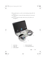
Remove the four screws that secure the display assembly to the top cover.
16
Lift the display assembly off the computer base.
Replacing the Display Assembly
1
Follow the instructions in "Before You Begin" on page 9.
2
Place the display assembly in position and replace the four screws that
secure the display assembly to the top cover.
3
Route the display cable through the routing guides.
4
Connect the display cable to the system-board connector.
5
Tighten the captive screw that secures the display grounding cable to the
top cover.
6
Connect the touch-screen cable to the system-board connector, if
applicable.
7
Route the Mini-Card antenna cables through the routing guides.
8
Connect the appropriate antenna cables to the Mini-Cards(s) on your
computer (see "Replacing the Mini-Card(s)" on page 23).
9
Replace the keyboard (see "Replacing the Keyboard" on page 45).
10
Replace the palm-rest assembly (see "Replacing the Palm-Rest Assembly"
11
Close the display and turn the computer over.
12
Replace the optical drive (see "Replacing the Optical Drive" on page 34).
13
Replace the two screws that secure the display assembly to the base cover.
14
Replace the module cover (see "Replacing the Module Cover" on page 16).
15
Replace the battery (see "Replacing the Battery" on page 14).
CAUTION:
Before turning on the computer, replace all screws and ensure that no
stray screws remain inside the computer. Failure to do so may result in damage to
the computer.
book.book Page 58 Wednesday, April 25, 2012 2:11 PM
Summary of Contents for XPS L702X
Page 12: ...12 Before You Begin book book Page 12 Wednesday April 25 2012 2 11 PM ...
Page 25: ...Wireless Mini Card s 25 book book Page 25 Wednesday April 25 2012 2 11 PM ...
Page 26: ...26 Wireless Mini Card s book book Page 26 Wednesday April 25 2012 2 11 PM ...
Page 32: ...32 Hard Drive s book book Page 32 Wednesday April 25 2012 2 11 PM ...
Page 35: ...Optical Drive 35 book book Page 35 Wednesday April 25 2012 2 11 PM ...
Page 36: ...36 Optical Drive book book Page 36 Wednesday April 25 2012 2 11 PM ...
Page 42: ...42 Palm Rest Assembly book book Page 42 Wednesday April 25 2012 2 11 PM ...
Page 50: ...50 Power Button Board book book Page 50 Wednesday April 25 2012 2 11 PM ...
Page 53: ...Coin Cell Battery 53 book book Page 53 Wednesday April 25 2012 2 11 PM ...
Page 54: ...54 Coin Cell Battery book book Page 54 Wednesday April 25 2012 2 11 PM ...
Page 74: ...74 IR Emitter Board book book Page 74 Wednesday April 25 2012 2 11 PM ...
Page 75: ...IR Emitter Board 75 book book Page 75 Wednesday April 25 2012 2 11 PM ...
Page 76: ...76 IR Emitter Board book book Page 76 Wednesday April 25 2012 2 11 PM ...
Page 82: ...82 Camera Module book book Page 82 Wednesday April 25 2012 2 11 PM ...
Page 89: ...Top Cover 89 book book Page 89 Wednesday April 25 2012 2 11 PM ...
Page 90: ...90 Top Cover book book Page 90 Wednesday April 25 2012 2 11 PM ...
Page 94: ...94 Subwoofer book book Page 94 Wednesday April 25 2012 2 11 PM ...
Page 98: ...98 AC Adapter Connector book book Page 98 Wednesday April 25 2012 2 11 PM ...
Page 102: ...102 Fan book book Page 102 Wednesday April 25 2012 2 11 PM ...
Page 103: ...Fan 103 book book Page 103 Wednesday April 25 2012 2 11 PM ...
Page 104: ...104 Fan book book Page 104 Wednesday April 25 2012 2 11 PM ...
Page 108: ...108 Heat Sink book book Page 108 Wednesday April 25 2012 2 11 PM ...
Page 109: ...Heat Sink 109 book book Page 109 Wednesday April 25 2012 2 11 PM ...
Page 110: ...110 Heat Sink book book Page 110 Wednesday April 25 2012 2 11 PM ...
Page 122: ...122 TV Antenna Connector book book Page 122 Wednesday April 25 2012 2 11 PM ...
Page 126: ...126 USB Board book book Page 126 Wednesday April 25 2012 2 11 PM ...
Page 132: ...132 System Board book book Page 132 Wednesday April 25 2012 2 11 PM ...


