background image

22

  |  Removing 

the 

Hard 

Drive

3

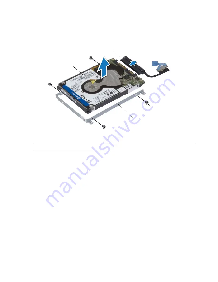
Lift the hard-drive assembly off the palm-rest assembly.

4

Disconnect the interposer from the hard-drive assembly.

5

Remove the screws that secure the hard-drive bracket to the hard drive.

6

Lift the hard drive off the hard-drive bracket.

1

hard drive

2

interposer

3

screws (4)

4

hard-drive bracket

2

1

4

3

Summary of Contents for XPS 9530

Page 1: ...XPS 15 Owner s Manual Computer model XPS 9530 Regulatory model P31F Regulatory type P31F001 ...

Page 2: ...AUTION A CAUTION indicates potential damage to hardware or loss of data if instructions are not followed WARNING A WARNING indicates a potential for property damage personal injury or death ____________________ 2013 Dell Inc Trademarks used in this text Dell the DELL logo and XPS are trademarks of Dell Inc 2013 10 Rev A00 ...

Page 3: ...dure 10 Replacing the Base Cover Assembly 12 Procedure 12 Removing the System Badge 13 Prerequisites 13 Procedure 13 Replacing the System Badge 15 Procedure 15 Postrequisites 15 Removing the Battery 16 Prerequisites 16 Procedure 16 Replacing the Battery 17 Procedure 17 Postrequisites 17 Removing the NFC card 18 Prerequisites 18 Procedure 18 Replacing the NFC card 19 Procedure 19 Postrequisites 19 ...

Page 4: ...Speakers 25 Procedure 25 Postrequisites 25 Removing the Wireless Card 26 Prerequisites 26 Procedure 26 Replacing the Wireless Card 27 Procedure 27 Postrequisites 27 Removing the Coin Cell Battery 28 Prerequisites 28 Replacing the Coin Cell Battery 29 Procedure 29 Postrequisites 29 Removing the mSATA Card 30 Prerequisites 30 Procedure 30 Replacing the mSATA Card 32 Procedure 32 Postrequisites 32 ...

Page 5: ...g Assembly 36 Procedure 36 Postrequisites 36 Removing the Power Adapter Port 37 Prerequisites 37 Procedure 37 Replacing the Power Adapter Port 38 Procedure 38 Postrequisites 38 Removing the I O Board 39 Prerequisites 39 Procedure 39 Replacing the I O Board 41 Procedure 41 Postrequisites 41 Removing the Memory Module s 42 Prerequisites 42 Procedure 42 Replacing the Memory Module s 43 Procedure 43 P...

Page 6: ...he Keyboard 50 Prerequisites 50 Procedure 50 Replacing the Keyboard 53 Procedure 53 Postrequisites 53 Removing the Display Assembly 54 Prerequisites 54 Procedure 55 Replacing the Display Assembly 58 Procedure 58 Postrequisites 58 Removing the Palm Rest Assembly 59 Prerequisites 59 Procedure 60 Replacing the Palm Rest Assembly 62 Procedure 62 Postrequisites 62 Flashing the BIOS 63 ...

Page 7: ... corner of the screen to open the Charms sidebar and then click Settings Power Shut down NOTE If you are using a different operating system see the documentation of your operating system for shut down instructions 3 After the computer shuts down disconnect it from the electrical outlet 4 Disconnect all cables such as power and USB cables from your computer 5 Disconnect all peripherals connected to...

Page 8: ...ur computer and protecting against electrostatic discharge CAUTION To avoid damaging the computer make sure that the work surface is flat and clean CAUTION When you disconnect a cable pull on its connector or on its pull tab not on the cable itself Some cables have connectors with locking tabs or thumb screws that you must disengage before disconnecting the cable When disconnecting cables keep the...

Page 9: ...ews inside your computer may severely damage your computer 1 Replace all screws and make sure that no stray screws remain inside your computer 2 Connect any cables peripherals and other parts you removed before working on your computer 3 Connect your computer to the electrical outlet 4 Turn on your computer ...

Page 10: ...g Inside Your Computer on page 7 After working inside your computer follow the instructions in After Working Inside Your Computer on page 9 For more safety best practices see the Regulatory Compliance home page at dell com regulatory_compliance Procedure 1 Close the display and turn the computer over 2 Turn the system badge over and place it on the base cover assembly 1 system badge 2 base cover a...

Page 11: ...emove the screws that secure the base cover assembly to the palm rest assembly 4 Using a plastic scribe pry the base cover assembly out of the palm rest assembly 1 screws 12 1 plastic scribe 2 base cover assembly 3 palm rest assembly 1 1 2 3 ...

Page 12: ...ur computer follow the instructions in After Working Inside Your Computer on page 9 For more safety best practices see the Regulatory Compliance home page at dell com regulatory_compliance Procedure 1 Place the base cover assembly on the palm rest assembly and snap it into place 2 Replace the screws that secure the base cover to the palm rest assembly 3 Turn the system badge over and snap it in pl...

Page 13: ...ng inside your computer follow the instructions in After Working Inside Your Computer on page 9 For additional safety best practices information see the Regulatory Compliance Homepage at dell com regulatory_compliance Prerequisites Remove the base cover assembly See Removing the Base Cover Assembly on page 10 Procedure 1 Peel the Mylars that secure the system badge to the base cover assembly 2 Tur...

Page 14: ...14 Removing the System Badge 3 Release the tab on the system badge from the slot on the base cover assembly 4 Lift the system badge off the base cover assembly 1 system badge 1 ...

Page 15: ...ter Working Inside Your Computer on page 9 For additional safety best practices information see the Regulatory Compliance Homepage at dell com regulatory_compliance Procedure 1 Slide the tab on the system badge into the slot on the base cover assembly and snap the system badge into place 2 Turn the base cover assembly over 3 Adhere the Mylars that secure the system badge to the base cover assembly...

Page 16: ... For more safety best practices see the Regulatory Compliance home page at dell com regulatory_compliance Prerequisites Remove the base cover assembly See Removing the Base Cover Assembly on page 10 Procedure 1 Remove the screws that secure the battery to the palm rest assembly 2 Disconnect the battery cable from the system board 3 Lift the battery off the palm rest assembly 4 Turn the computer ov...

Page 17: ...ructions in After Working Inside Your Computer on page 9 For more safety best practices see the Regulatory Compliance home page at dell com regulatory_compliance Procedure 1 Align the screw holes on the battery with the screw holes on the palm rest assembly 2 Replace the screws that secure the battery to the palm rest assembly 3 Connect the battery cable to the system board Postrequisites Replace ...

Page 18: ...actices information see the Regulatory Compliance Homepage at dell com regulatory_compliance Prerequisites 1 Remove the base cover assembly See Removing the Base Cover Assembly on page 10 2 Remove the battery See Removing the Battery on page 16 Procedure 1 Peel off the adhesive foams from the NFC card and the NFC cable 2 Lift the connector latches and disconnect the NFC cable and the antenna cable...

Page 19: ...ractices information see the Regulatory Compliance Homepage at dell com regulatory_compliance Procedure 1 Use the alignment posts on the palm rest assembly to place the NFC card on the palm rest assembly 2 Slide the NFC and antenna cables in the respective connectors on the NFC card and press down on the connector latches to secure the cables 3 Adhere the adhesive foams to the NFC card and NFC cab...

Page 20: ...orking Inside Your Computer on page 9 For additional safety best practices information see the Regulatory Compliance Homepage at dell com regulatory_compliance CAUTION To avoid data loss do not remove the hard drive while the computer is On or in Sleep state CAUTION Hard drives are extremely fragile Exercise care when handling the hard drive Prerequisites 1 Remove the base cover assembly See Remov...

Page 21: ...rive 21 Procedure 1 Remove the screws that secure the hard drive assembly to the palm rest assembly 2 Using the pull tab disconnect the hard drive cable from the system board 1 hard drive cable 2 pull tab 3 screws 4 1 3 2 ...

Page 22: ...e palm rest assembly 4 Disconnect the interposer from the hard drive assembly 5 Remove the screws that secure the hard drive bracket to the hard drive 6 Lift the hard drive off the hard drive bracket 1 hard drive 2 interposer 3 screws 4 4 hard drive bracket 2 1 4 3 ...

Page 23: ...are extremely fragile Exercise care when handling the hard drive Procedure 1 Align the screw holes on the hard drive bracket with the screw holes on the hard drive 2 Replace the screws that secure the hard drive bracket to the hard drive 3 Connect the interposer to the hard drive assembly 4 Align the screw holes on the hard drive assembly with the screw holes on the palm rest assembly 5 Replace th...

Page 24: ...s see the Regulatory Compliance home page at dell com regulatory_compliance Prerequisites 1 Remove the base cover assembly See Removing the Base Cover Assembly on page 10 2 Remove the battery See Removing the Battery on page 16 Procedure 1 Disconnect the speaker cable from the system board 2 Note the speaker cable routing and remove the cable from the routing guides 3 Remove the screw that secures...

Page 25: ...t practices see the Regulatory Compliance home page at dell com regulatory_compliance Procedure 1 Using the alignment posts on the palm rest assembly place the speakers on the palm rest assembly 2 Replace the screw that secures the speakers to the palm rest assembly 3 Route the speaker cable through the routing guides on the palm rest assembly 4 Connect the speaker cable to the system board Postre...

Page 26: ...best practices see the Regulatory Compliance home page at dell com regulatory_compliance Prerequisites 1 Remove the base cover assembly See Removing the Base Cover Assembly on page 10 2 Remove the battery See Removing the Battery on page 16 Procedure 1 Remove the screw that secures the wireless card bracket and wireless card to the palm rest assembly 2 Disconnect the antenna cables from the wirele...

Page 27: ...nector on the I O board 2 Align the screw hole on the wireless card to the screw hole on the palm rest assembly 3 Connect the antenna cables to the wireless card 4 Align the screw hole on the wireless card bracket with the screw hole on the wireless card 5 Replace the screw that secures the wireless card bracket and the wireless card to the palm rest assembly NOTE The color of the antenna cables i...

Page 28: ... page at dell com regulatory_compliance CAUTION Removing the coin cell battery resets the BIOS settings to default It is recommended that you note the BIOS settings before removing the coin cell battery Prerequisites 1 Remove the base cover assembly See Removing the Base Cover Assembly on page 10 2 Remove the battery See Removing the Battery on page 16 3 Remove the wireless card See Removing the W...

Page 29: ...pliance home page at dell com regulatory_compliance WARNING The battery may explode if installed incorrectly Replace the battery only with the same or equivalent type Discard used batteries according to the manufacturer s instructions Procedure 1 Adhere the coin cell battery into its position on the palm rest assembly 2 Connect the coin cell battery cable to the I O board Postrequisites 1 Replace ...

Page 30: ...de your computer follow the instructions in After Working Inside Your Computer on page 9 For more safety best practices see the Regulatory Compliance home page at dell com regulatory_compliance Prerequisites 1 Remove the base cover assembly See Removing the Base Cover Assembly on page 10 2 Remove the battery See Removing the Battery on page 16 Procedure 1 Disconnect the I O board cable from the sy...

Page 31: ...Removing the mSATA Card 31 2 Remove the screw that secures the mSATA card to the palm rest assembly 3 Slide and remove the mSATA card from the system board 1 mSATA card 2 screw 1 2 ...

Page 32: ...ory Compliance home page at dell com regulatory_compliance Procedure 1 Align the notch on the mSATA card with the tab on the mSATA card connector 2 Insert the mSATA card into the mSATA card connector 3 Align the screw hole on the mSATA card with the screw hole on the palm rest assembly 4 Replace the screw that secures the mSATA card to the palm rest assembly 5 Connect the I O board cable to the sy...

Page 33: ...For more safety best practices see the Regulatory Compliance home page at dell com regulatory_compliance Prerequisites 1 Remove the base cover assembly See Removing the Base Cover Assembly on page 10 2 Remove the battery See Removing the Battery on page 16 Procedure 1 Remove the screws that secure the fans to the system board 2 Disconnect the camera cable from the I O board 3 Disconnect the fan ca...

Page 34: ...age 9 For more safety best practices see the Regulatory Compliance home page at dell com regulatory_compliance Procedure 1 Connect the fan cables to the system board 2 Connect the camera cable to the I O board 3 Align the screw holes on the fans with the screw holes on the palm rest assembly 4 Replace the screws that secure the fans to the palm rest assembly Postrequisites 1 Replace the battery Se...

Page 35: ...ompliance home page at dell com regulatory_compliance Prerequisites 1 Remove the base cover assembly See Removing the Base Cover Assembly on page 10 2 Remove the battery See Removing the Battery on page 16 Procedure NOTE The appearance of the thermal cooling assembly and the number of screws will vary if you purchased your computer with integrated graphics card 1 In sequential order indicated on t...

Page 36: ...e Your Computer on page 9 For more safety best practices see the Regulatory Compliance home page at dell com regulatory_compliance Procedure 1 Align the screw holes on the thermal cooling assembly with the screw holes on the system board 2 In sequential order indicated on the cooling assembly tighten the captive screws that secure the thermal cooling assembly to the system board Postrequisites 1 R...

Page 37: ...e page at dell com regulatory_compliance Prerequisites 1 Remove the base cover assembly See Removing the Base Cover Assembly on page 10 2 Remove the battery See Removing the Battery on page 16 Procedure 1 Disconnect the power adapter port cable from the system board 2 Disconnect the touch panel cable from the system board 3 Release the power adapter port cable from under the display hinge 4 Remove...

Page 38: ...ee the Regulatory Compliance home page at dell com regulatory_compliance Procedure 1 Align the screw hole on the power adapter port with the screw hole on the palm rest assembly 2 Replace the screw that secures the power adapter port to the palm rest assembly 3 Route the power adapter port cable under the display hinge 4 Connect the touch panel cable to the system board 5 Connect power adapter por...

Page 39: ...de Your Computer on page 9 For additional safety best practices information see the Regulatory Compliance Homepage at dell com regulatory_compliance Prerequisites 1 Remove the base cover assembly See Removing the Base Cover Assembly on page 10 2 Remove the battery See Removing the Battery on page 16 3 Remove the wireless card See Removing the Wireless Card on page 26 Procedure 1 Using the pull tab...

Page 40: ...ell battery cable and camera cable from the I O board 3 Remove the screws that secure the I O board to the palm rest assembly 4 Lift the I O board from the palm rest assembly 1 fan cable 2 coin cell battery cable 3 camera cable 1 I O board 2 screws 3 1 2 3 1 2 ...

Page 41: ...Compliance Homepage at dell com regulatory_compliance Procedure 1 Align the screw holes on the I O board with the screw holes on the palm rest assembly 2 Replace the screws that secure the I O board to the palm rest assembly 3 Connect the camera cable coin cell battery cable and fan cable to the I O board 4 Connect the I O board cable to the I O board and the system board Postrequisites 1 Replace ...

Page 42: ... 9 For more safety best practices see the Regulatory Compliance home page at dell com regulatory_compliance Prerequisites 1 Remove the base cover assembly See Removing the Base Cover Assembly on page 10 2 Remove the battery See Removing the Battery on page 16 Procedure 1 Use your fingertips to carefully spread apart the securing clips on each end of the memory module connector until the memory mod...

Page 43: ...safety best practices see the Regulatory Compliance home page at dell com regulatory_compliance Procedure 1 Align the notch on the memory module with the tab on the memory module connector 2 Slide the memory module firmly into the connector at a 45 degree angle and press the memory module down until it clicks into place NOTE If you do not hear the click remove the memory module and reinstall it Po...

Page 44: ...9 For more safety best practices see the Regulatory Compliance home page at dell com regulatory_compliance Prerequisites 1 Remove the base cover assembly See Removing the Base Cover Assembly on page 10 2 Remove the battery See Removing the Battery on page 16 3 Remove the fans See Removing the Fans on page 33 4 Remove the thermal cooling assembly See Removing the Thermal Cooling Assembly on page 35...

Page 45: ... Tag in the BIOS after you replace the system board NOTE Before disconnecting the cables from the system board note the location of the connectors so that you can reconnect them correctly after you replace the system board 1 Using the pull tabs disconnect the I O board cable from the system board 1 I O board cable 2 pull tabs 2 1 2 ...

Page 46: ... Lift the connector latches and disconnect the keyboard backlight cable the touchpad cable the NFC cable and the hard drive cable from the system board 5 Peel off the tape lift the connector latch and disconnect the keyboard cable from the system board 1 power adapter port cable 2 touch panel cable 3 display cable 4 hard drive cable 5 speaker cable 6 NFC cable 7 keyboard cable 8 touchpad cable 9 k...

Page 47: ...crews that secure the system board to the palm rest assembly 7 Loosen the captive screws that secure the system board to the palm rest assembly 8 Lift the system board off the palm rest assembly 1 captive screws 2 2 system board 3 screws 4 1 2 3 ...

Page 48: ... rest assembly 4 Replace the screws that secure the system board to the palm rest assembly 5 Slide the keyboard cable in the connector and press down on the connector latch to secure the cable 6 Adhere the tape to the keyboard cable connector 7 Slide the keyboard backlight cable touchpad cable NFC cable and hard drive cable into the system board and press down on the connector latches to secure th...

Page 49: ...ng the System Board 49 Entering the Service Tag in the BIOS 1 Turn on the computer 2 At the Dell logo press F2 to enter System Setup 3 Navigate to the Main tab and type the Service Tag in the Service Tag field ...

Page 50: ...er Working Inside Your Computer on page 9 For more safety best practices see the Regulatory Compliance home page at dell com regulatory_compliance Prerequisites 1 Remove the base cover assembly See Removing the Base Cover Assembly on page 10 2 Remove the battery See Removing the Battery on page 16 3 Remove the hard drive See Removing the Hard Drive on page 20 4 Remove the system board See Removing...

Page 51: ...ving the Keyboard 51 2 Using a plastic scribe peel the Mylar to access the screws 3 Remove the screws that secure the keyboard to the palm rest assembly 1 plastic scribe 2 mylar 3 screw 1 screws 28 1 2 3 1 ...

Page 52: ...52 Removing the Keyboard 4 Lift and remove the keyboard from the palm rest assembly 1 keyboard 2 palm rest assembly 2 1 ...

Page 53: ...nce home page at dell com regulatory_compliance Procedure 1 Align the screw holes on the keyboard with the screw holes on the palm rest assembly 2 Replace the screws that secure the keyboard to the palm rest assembly 3 Adhere the Mylar to the screws on the keyboard 4 Adhere the Mylar the keyboard Postrequisites 1 Replace the system board See Replacing the System Board on page 48 2 Replace the hard...

Page 54: ...orking Inside Your Computer on page 7 After working inside your computer follow the instructions in After Working Inside Your Computer on page 9 For more safety best practices see the Regulatory Compliance home page at dell com regulatory_compliance Prerequisites 1 Remove the base cover assembly See Removing the Base Cover Assembly on page 10 2 Remove the battery See Removing the Battery on page 1...

Page 55: ...bly 2 Disconnect the antenna cables from the wireless card 3 Disconnect the touch panel cable and display cable from the system board 4 Disconnect the camera cable from the I O board 5 Remove the cables from their routing guides 1 screw 2 wireless card bracket 3 antenna cables 2 4 touch panel cable 5 display cable 6 camera cable 1 3 4 5 6 2 ...

Page 56: ...ove the screws that secure the display hinges to the palm rest assembly 7 Carefully lift the palm rest assembly away from the display assembly as far as possible 1 screws 6 2 display hinges 2 1 palm rest assembly 2 display assembly 2 1 1 2 ...

Page 57: ...lowly to avoid damaging the display assembly 8 Close the palm rest assembly to release the tabs on the palm rest assembly from the display hinges 9 Slide the palm rest assembly away from the display assembly 1 display hinges 2 2 palm rest assembly 3 display assembly 2 3 1 ...

Page 58: ...the display assembly 2 Align the screw holes on the display hinges with the screw holes on the palm rest assembly 3 Replace the screws that secure the display hinges to the palm rest assembly 4 Press down on the palm rest assembly to close the display 5 Route the touch panel cable display cable and camera cable through the routing guides 6 Connect the touch panel cable and display cable to the sys...

Page 59: ...move the hard drive See Removing the Hard Drive on page 20 4 Remove the speakers See Removing the Speakers on page 24 5 Remove the wireless card See Removing the Wireless Card on page 26 6 Remove the coin cell battery See Removing the Coin Cell Battery on page 28 7 Remove the mSATA card See Removing the mSATA Card on page 30 8 Remove the fans See Removing the Fans on page 33 9 Remove the thermal c...

Page 60: ... 1 Remove the screws that secure the display hinges to the palm rest assembly 2 Carefully lift the palm rest assembly away from the display assembly as far as possible 1 screws 6 2 display hinges 2 1 palm rest assembly 2 display assembly 1 2 1 2 ...

Page 61: ... slowly to avoid damaging the display assembly 3 Close the palm rest assembly to release the tabs on the palm rest assembly from the display hinges 4 Slide the palm rest assembly away from the display assembly 1 display hinges 2 palm rest assembly 3 display assembly 2 3 1 ...

Page 62: ...oard on page 48 3 Replace the memory modules See Replacing the Memory Module s on page 43 4 Replace the I O board See Replacing the I O Board on page 41 5 Replace the power adapter port See Replacing the Power Adapter Port on page 38 6 Replace the thermal cooling assembly See Replacing the Thermal Cooling Assembly on page 36 7 Replace the fans See Replacing the Fans on page 34 8 Replace the mSATA ...

Page 63: ... of the Service Tag NOTE If the Service Tag cannot be detected automatically select your product under the product categories 4 Click Drivers and Downloads 5 In the Operating System drop down select the operating system installed on your computer 6 Click BIOS 7 Click Download File to download the latest version of the BIOS for your computer 8 On the next page select Single file download and click ...

Reviews: