background image

Installing the WLAN card

1.

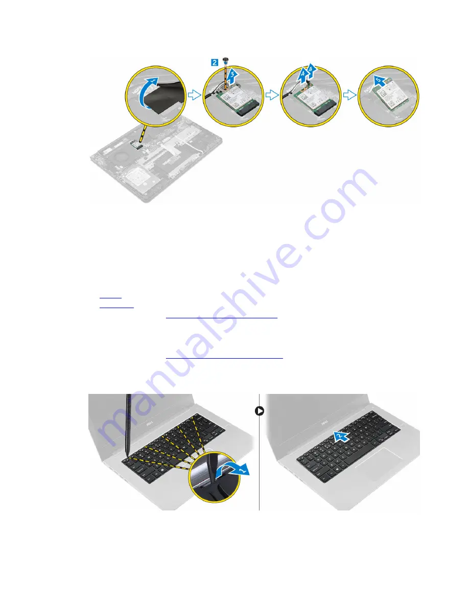
Insert the WLAN card into the connector at a 45–degree angle.

2.

Tighten the screw to secure the WLAN card to the computer.

3.

Connect the antenna cables to the connectors marked on the WLAN card.

4.

Close the plastic cover over the WLAN card.

5.

Install the:
a.

battery

b.

back cover

6.

Follow the procedure in 

After working inside your computer

Removing the keyboard

1.

Follow the procedure in 

Before working inside your computer

.

2.

To remove the keyboard:
a. Using a plastic scribe, lift the edges of the keyboard at the locations indicated [1].
b. Slide the keyboard toward the display to release it from the computer [2].

3.

To disconnect the keyboard cable:

12

Summary of Contents for Vostro 14-5459

Page 1: ...Vostro 14 5459 Owner s Manual Regulatory Model P68G Regulatory Type P68G001 ...

Page 2: ... by U S and international copyright and intellectual property laws Dell and the Dell logo are trademarks of Dell Inc in the United States and or other jurisdictions All other marks and names mentioned herein may be trademarks of their respective companies 2015 10 Rev A00 ...

Page 3: ...ory module 11 Removing the WLAN card 11 Installing the WLAN card 12 Removing the keyboard 12 Installing the keyboard 13 Removing the speakers 13 Installing the speakers 14 Removing the heat sink 14 Installing the heat sink 14 Removing the fan 15 Installing the fan 15 Removing the display assembly 15 Installing the display assembly 16 Removing the display bezel 17 Installing the display bezel 17 Re...

Page 4: ...em Setup overview 23 Boot Sequence 23 Navigation keys 23 Updating the BIOS 24 System Setup options 25 4 Troubleshooting 27 Enhanced Pre Boot System Assessment ePSA diagnostics 27 LED error codes 27 Battery status lights 28 5 Specifications 29 6 Contacting Dell 34 Contacting Dell 34 4 ...

Page 5: ...epairs as authorized in your product documentation or as directed by the online or telephone service and support team Damage due to servicing that is not authorized by Dell is not covered by your warranty Read and follow the safety instructions that came with the product CAUTION To avoid electrostatic discharge ground yourself by using a wrist grounding strap or by periodically touching an unpaint...

Page 6: ...e cover CAUTION Before touching anything inside your computer ground yourself by touching an unpainted metal surface such as the metal at the back of the computer While you work periodically touch an unpainted metal surface to dissipate static electricity which could harm internal components Turning off your computer CAUTION To avoid losing data save and close all open files and exit all open prog...

Page 7: ...l devices cards and cables before turning on your computer CAUTION To avoid damage to the computer use only the battery designed for this particular Dell computer Do not use batteries designed for other Dell computers 1 Connect any external devices such as a port replicator or media base and replace any cards such as an ExpressCard 2 Connect any telephone or network cables to your computer CAUTION...

Page 8: ...e Removing the back cover 1 Follow the procedures in Before working inside your computer 2 To remove the back cover a Remove the screws that secure the back cover to the computer 1 b Pry the edges of the back cover from all sides to release the back cover 2 3 4 5 c Lift the back cover from the computer 6 Installing the back cover 1 Align the back cover with the screw holes on the computer 2 Tighte...

Page 9: ...e slot on the computer 2 Install the screws that secure the battery to the computer 3 Connect the battery cable to the connector on the system board 4 Install the back cover 5 Follow the procedure in After working inside your computer Removing the hard drive 1 Follow the procedure in Before working inside your computer 2 Remove the a back cover b battery 3 To remove the hard drive a Disconnect the...

Page 10: ... back cover 5 Follow the procedure in After working inside your computer Removing the memory module 1 Follow the procedure in Before working inside your computer 2 Remove the a back cover b battery 3 To remove the memory module a Lift the plastic enclosure covering the top of the memory module compartment 1 b Pull the retention clips from the memory module until it pops up 2 c Remove the memory mo...

Page 11: ... 5 Follow the procedure in After working inside your computer Removing the WLAN card 1 Follow the procedures in Before working inside your computer 2 Remove the a back cover b battery 3 To remove WLAN card a Lift the plastic flap which covers the WLAN card 1 b Remove the screw that secures the WLAN card to the computer 2 3 c Disconnect the antenna cable from the WLAN card 4 d Remove the WLAN card ...

Page 12: ...astic cover over the WLAN card 5 Install the a battery b back cover 6 Follow the procedure in After working inside your computer Removing the keyboard 1 Follow the procedure in Before working inside your computer 2 To remove the keyboard a Using a plastic scribe lift the edges of the keyboard at the locations indicated 1 b Slide the keyboard toward the display to release it from the computer 2 3 T...

Page 13: ...along the edges 3 Press the edges of the keyboard until clicks into place 4 Follow the procedure in After working inside your computer Removing the speakers 1 Follow the procedure in Before working inside your computer 2 Remove the a back cover b battery c hard drive 3 To remove the speakers a Disconnect the speaker cable from the system board and unroute it along the routing channel 1 b Lift the ...

Page 14: ...inside your computer 2 Remove the a back cover b battery 3 To remove the heat sink a Lift the plastic flap that covers the memory module to access the heat sink module 1 b Remove the screws that secure the heat sink module to the computer chassis 2 3 4 5 6 7 c Remove the heat sink module from the slot on the system board 8 Installing the heat sink 1 Place the heat sink module into its slot on the ...

Page 15: ...em board 2 c Remove the screws that secure the fan module to the system board 3 d Lift the fan module from the computer Installing the fan 1 Install the fan into the slot on the system board 2 Tighten the screws to secure the fan module 3 Connect the I O and system board cables to the system board connectors 4 Install the a WLAN card b battery c back cover 5 Follow the procedure in After working i...

Page 16: ...the display hinges to the computer chassis 4 4 To remove the display a Lift the computer chassis b Lift the computer chassis from the display Installing the display assembly 1 Align the display assembly with the display hinges of the computer chassis 2 Tighten the screws that secure the display hinges 3 Connect the display cable to the connector on the system board 4 Install the a heat sink b WLAN...

Page 17: ...splay bezel a Lift the corners of the bezel with a plastic scribe to remove it 1 2 3 4 Installing the display bezel 1 Place the display bezel on the display panel and press along the edges until it clicks in place 2 Install the a display assembly b heat sink c WLAN card d battery e back cover 3 Follow the procedure in After working inside your computer Removing the display panel 1 Follow the proce...

Page 18: ...1 Connect the display panel cable to the display panel and turn it over to align it with the assembly 2 Install the screws that secure the display panel 3 Install the a display bezel b display assembly c heat sink d WLAN card e battery f back cover 4 Follow the procedure in After working inside your computer Removing the I O panel 1 Follow the procedure in Before working inside your computer 2 Rem...

Page 19: ... board 3 Install the a fan b heat sink c WLAN card d battery e back cover 4 Follow the procedure in After working inside your computer Removing the power connector 1 Follow the procedure in Before working inside your computer 2 Remove the a back cover b battery c heat sink d WLAN card e display assembly 3 To remove the power connector a Disconnect the power connector cable from the system board 1 ...

Page 20: ...e a display assembly b heat sink c WLAN card d battery e back cover 4 Follow the procedure in After working inside your computer Removing the camera 1 Follow the procedure in Before working inside your computer 2 Remove the a back cover b battery c display assembly d display bezel 3 Disconnect the camera cable and lift the camera to remove it from the computer 1 2 20 ...

Page 21: ... the system board 1 Follow the procedure in Before working inside your computer 2 Remove the a back cover b battery c heat sink d WLAN card e fan f display assembly g power connector h IO Panel i memory module j speakers 3 To remove the system board a Disconnect the display assembly cable from the system board 1 2 b Remove the screws that secure the system board to the computer chassis 3 c Lift an...

Page 22: ...the system board to the computer chassis 3 Connect the display assembly cable to the system board 4 Install the a memory module b fan c speakers d keyboard e hard drive f IO panel g power connector h display assembly i heat sink j WLAN card k battery l back cover 5 Follow the procedure in After working inside your computer 22 ...

Page 23: ... incorrectly Boot Sequence Boot Sequence allows you to bypass the System Setup defined boot device order and boot directly to a specific device for example hard drive During the Power on Self Test POST when the Dell logo appears you can Access System Setup by pressing F2 key Bring up the one time boot menu by pressing F12 key The one time boot menu displays the devices that you can boot from inclu...

Page 24: ...e computer 2 Go to Dell com support 3 Enter the Service Tag or Express Service Code and click Submit NOTE To locate the Service Tag click Where is my Service Tag NOTE If you cannot find your Service Tag click Detect My Product Proceed with the instructions on screen 4 If you are unable to locate or find the Service Tag click the Product Category of your computer 5 Choose the Product Type from the ...

Page 25: ...ixed HDD Displays the model number and capacity of the hard drive mSATA Device Displays the model number and capacity of the optical drive System Memory Displays the memory in built on the computer Extended Memory Displays the memory installed on the computer Memory Speed Displays the memory speed Table 3 Advanced Intel SpeedStep Enable or disable the Intel SpeedStep feature Default Enabled Virtua...

Page 26: ... or delete the system password Set HDD Password Allows you to set a password on the computer s internal hard drive HDD Password Change Allows you to change the security password Password Bypass Allows you to bypass the system password and the internal HDD password prompts during a system restart resume from hibernate state Table 5 Boot Boot Priority Order Specifies the order of different devices i...

Page 27: ...ics to test only your computer Using this program with other computers may cause invalid results or error messages NOTE Some tests for specific devices require user interaction Always ensure that you are present at the computer terminal when the diagnostic tests are performed 1 Power on the computer 2 As the computer boots press the F12 key as the Dell logo appears 3 On the boot menu screen select...

Page 28: ...ipset failure 2 7 Display failure LCD 3 1 RTC Power failure 3 2 PCI video 3 3 BIOS recovery 1 3 4 BIOS recovery 2 4 1 CPU configuration or CPU failure 4 2 Generic POST video error old LED pattern 1110 Battery status lights Table 7 Battery LED Behavior Battery charge LED Status LED behavior AC mode All White Fully charged Off Battery mode Low to Fully charged Off Discharging when Battery charge is ...

Page 29: ...e 8 System Information Feature Description Chipset 6th generation Intel Core i3 Processor 6th generation Intel Core i5 Processor 6th generation Intel Core i7 Processor Chipset Integrated in processor Table 9 Memory Feature Description Slot One SODIMM slot Memory type DDR3L Speed 1600 MHz Configurations supported 4 GB and 8 GB Table 10 Audio Feature Description Controller Conexant CX6008 with Waves...

Page 30: ...card slot Supports SD 3 0 Table 14 Camera Feature Description Image resolution 0 92 megapixel Video Resolution maximum 1280 x 720 pixels HD at 30 fps Diagonal viewing angle 74 degree Table 15 Communication Feature Description Ethernet 10 100 1000 Mbps Ethernet controller integrated on system board Wireless 2x2 802 11 a b g n AC BT 1x1 802 11 a b g n AC BT Bluetooth 4 0 Intel WiDi Wi Fi Display Tab...

Page 31: ...m 8 12 inches Width 326 18 mm 12 84 inches Diagonal 14 0 Active area X Y 309 4 mm 12 18 inches x 173 95 mm 6 84 inches Maximum resolution 1366 x 768 pixels Maximum Brightness 200 nits Operating angle 135 degree Refresh rate 60 Hz 40 Hz Minimum Viewing angles Horizontal 40 L 40 R Vertical 10 up 30 down Pixel pitch 0 2265 H x 0 2265 V mm Table 18 Keyboard Feature Description Number of keys 80 Table ...

Page 32: ...operating 0 to 65 Coin cell battery LI 3V 83 MAH Table 21 AC adapter Feature Description Type 45 W 65 W Input voltage 100 240 V AC Input current maximum 45 W 1 3 A 65 W 1 6 A 1 7 A Input frequency 50 Hz 60 Hz Output current 45 W 2 31 A 65 W 3 34 A Rated output voltage 19 5 V DC Temperature range Operating 0 to 40 Non Operating 40 to 70 Table 22 Physical Feature Non touch Touch Height 18 30 mm 0 72...

Page 33: ...nvironmental Feature Description Temperature Operating 0 to 35 Storage 20 to 60 Relative humidity maximum Operating 20 90 Storage 20 95 Altitude maximum Operating 15 2 m to 3048 m 50 to 10 000 ft 0 to 35 C Non operating 15 2 m to 10 668 m 50 ft to 35 000 ft Airborne contaminant level G2 or lower as defined by ISA S71 04 1985 33 ...

Page 34: ... based support and service options Availability varies by country and product and some services may not be available in your area To contact Dell for sales technical support or customer service issues 1 Go to Dell com support 2 Select your support category 3 Verify your country or region in the Choose a Country Region drop down list at the bottom of the page 4 Select the appropriate service or sup...

Reviews: