background image

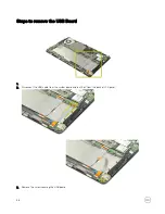
4.

Remove the USB board.

5.

USB board removal complete.

39

Summary of Contents for Venue Pro 11-7139

Page 1: ...Dell Venue Pro 11 7139 Disassembly Guide Regulatory Model T07G Regulatory Type T07G001 ...

Page 2: ......

Page 3: ...move the Front Camera 19 Steps to remove the I O Board 20 Steps to remove the micro SIM board 22 Steps to remove the Power switch board 23 Steps to remove the Rear camera 25 Steps to remove the SD card 26 Steps to remove the SmartCard reader 28 Steps to remove the Speakers 30 Steps to remove the Solid state drive SSD 32 Steps to remove the System Board 33 Steps to remove the Thermal Fan 35 Steps t...

Page 4: ...weezer NOTE The Venue 11 Pro 7139 does not contain any user serviceable components All repairs need to be performed by an authorized Dell technician only Dell is not responsible for any damage to the tablet due to unauthorized component disassembly or repairs This document is developed to meet the EPEAT regulatory compliance requirements Please refer to the User s guide on www Dell com support for...

Page 5: ... Disassembly Steps to remove the Back Cover 1 Use a scribe to pry up the recess hole on the back cover 2 Lift to remove the back cover 3 The following image shows the inside of the system after the back cover is removed 5 ...

Page 6: ...ry as much as possible before removing from the system This can be done by disconnecting the A C adapter from the system while the system is turned on to allow the system to drain the battery 1 2 Slide the battery release latch into the unlock position 6 ...

Page 7: ... from the computer Do not apply pressure to the surface of the battery Do not bend Do not use tools of any kind to pry on or against the battery If a battery cannot be removed within the constraints above please contact Dell technical support 7 ...

Page 8: ...4 Battery removal complete Steps to remove the Base Cover 1 2 Remove the two connector covers from the bottom case 8 ...

Page 9: ...3 Disconnect the docking FPC 1 and docking board cable 2 from the system board 9 ...

Page 10: ...10 ...

Page 11: ...4 5 6 11 ...

Page 12: ...7 8 Base removal complete 12 ...

Page 13: ...Steps to remove the Coin cell Battery 1 2 Disconnect the coin cell battery connector from the system board 3 Remove the coin cell battery 13 ...

Page 14: ...4 Coin cell battery removal complete Steps to remove the Docking Board 1 2 Unthread the docking board cable from the bottom case 14 ...

Page 15: ...3 Remove the screws securing the docking board in place 4 Lift to remove the docking board from the bottom case 5 Docking board removal complete 15 ...

Page 16: ...teps to remove the Fingerprint reader 1 2 Remove the two connector covers from the bottom case 3 Disconnect the docking FPC 1 docking board cable 2 and fingerprint reader cable 3 from the system board 16 ...

Page 17: ...docking FPC from the back of the LCD panel 5 Remove the screws from the bottom case 6 Use a plastic scribe to insert to the gap between the top case and bottom case pry all edges of the tablet to release all hooks 17 ...

Page 18: ...m the back of the bottom case peel off the cables on top of the fingerprint reader 8 Peel off the fingerprint reader cable from the bottom case and remove the reader 9 Fingerprint reader removal complete 18 ...

Page 19: ...Steps to remove the Front Camera 1 2 Disconnect the rear camera cable from the front camera 3 Lift to separate the front camera 19 ...

Page 20: ...4 Front camera removal complete Steps to remove the I O Board 1 2 Disconnect the HDMI FPC from the system board and tear it off from the back of the LCD panel 20 ...

Page 21: ...3 Remove the I O board 4 I O Board removal complete 21 ...

Page 22: ...Steps to remove the micro SIM board 1 2 Press in the micro SIM card and release 3 Slide out the SIM card from its slot using a pair of tweezer 22 ...

Page 23: ...4 micro SIM board removal complete Steps to remove the Power switch board 1 2 Disconnect the power cable from the power switch board 23 ...

Page 24: ...3 Remove the screw from the power switch board 4 Remove the power switch board 5 Power switch board removal complete 24 ...

Page 25: ...Steps to remove the Rear camera 1 2 Disconnect the rear camera cable from the front camera 3 Lift to separate the rear camera 25 ...

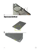
Page 26: ...4 Rear camera removal complete Steps to remove the SD card 1 2 Insert an unfolded paper clip into the small hole on the micro SD card cap and release 26 ...

Page 27: ...3 Slide the micro SD card cap out of the system 4 SD card removal complete 27 ...

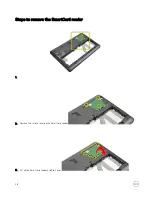
Page 28: ...Steps to remove the SmartCard reader 1 2 Remove the screws securing the SmartCard reader 3 Lift up the SmartCard reader and flip it over 28 ...

Page 29: ...4 Disconnect the cables from the SmartCard reader using a pair of tweezer 5 Remove the SmartCard reader from the tablet 6 SmartCard removal complete 29 ...

Page 30: ...Steps to remove the Speakers 1 2 Lift up the speaker from the adhesive tape on the right and unthread its cable 30 ...

Page 31: ...3 Remove the adhesive tapes on the speaker cables and remove the speaker module from the system 4 Speaker removal complete 31 ...

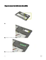
Page 32: ...Steps to remove the Solid state drive SSD 1 2 Remove the screw from the SSD 3 SSD removal complete 32 ...

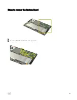
Page 33: ...Steps to remove the System Board 1 2 Unthread all the antenna cables from its routing channel 33 ...

Page 34: ...the system board thermal fan cable vibration motor cable HDMI cable power cable camera cable speaker cable USB cable and LCM FPC on the LCD assembly 4 Remove the screws securing the system board 5 Remove the system board from the system 34 ...

Page 35: ...6 System board removal complete Steps to remove the Thermal Fan 1 2 Tear off the adhesive tape 35 ...

Page 36: ...3 Lift up the thermal fan cable 4 Disconnect the thermal fan cable from the system board 5 Remove the screws securing the thermal fan 36 ...

Page 37: ...6 Remove the thermal fan from the system 7 Thermal fan removal complete 37 ...

Page 38: ...Steps to remove the USB Board 1 2 Disconnect the USB cable from the system board and tear it off from the back of LCD panel 3 Remove the screw securing the USB board 38 ...

Page 39: ...4 Remove the USB board 5 USB board removal complete 39 ...

Page 40: ...Steps to remove the WWAN card 1 2 Disconnect the antenna cables from the WWAN card using a pair of tweezer 3 Remove the screw from the WWAN card 40 ...

Page 41: ...4 WWAN card removal complete Steps to remove the WLAN Card 1 2 Tear off the mylar tape covering the WLAN card 41 ...

Page 42: ...3 Disconnect the antenna cables from the WLAN card using a pair of tweezer 4 Remove the screw from the WLAN card 5 Remove the WLAN card from the system 42 ...

Page 43: ...6 WLAN card removal complete 43 ...

Reviews: