Dell UltraSharp U2421HE Service Manual Download Page 6

  4. Disassembly and Assembly Procedures

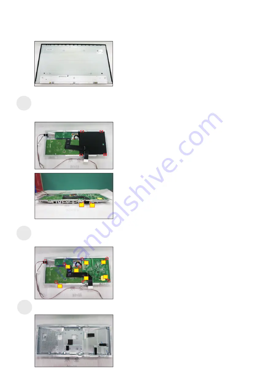
Remove the circuit boards from the 

disconnect all of the cables.

bracket 

carefully, and then 

 S15

Turn over the bracket chassis module. Remove the 

Mylar from the hooks of the bracket, and then use a 

Philips-head screwdriver to remove 

screws for 

unlocking AC power outlet.  

two 

(No.1~2 screw size=M3x10, Torque=6

±0.5

kgfxcm)

 S16

S14

2

1

Use a Philips-head screwdriver to remove 

screws 

for unlocking power board and interface board.  

7pcs 

(No.1 screw size=M4x8, Torque=6

±0.5

kgfxcm; 

 No.2~7 screw size=M3x7.5, Torque=6

±0.5

kgfxcm)

2

1

4

4

5

6

7

Summary of Contents for UltraSharp U2421HE

Page 1: ...ipment or products It is recommended that service engineers should have repairing knowledge experience as well as appropriate product training per new model before performing the service procedures NOTICE To avoid electrical shocks the products should be connected to an authorized power cord and turn off the master power switch each time before removing the AC power cord To prevent the product awa...

Page 2: ...2 Exploded view diagram with list of items Panel Power Button OSD Button Front trim Key board Key mylar Power myalr Power board Interface board Stand Back Cover Main chassis Key Board ...

Page 3: ...3 Wiring Connectivity Diagram Audio out LED DRIVER HDMI1 DP1 DP2 USB1 USB2 USB3 Panel Interface board FK board USB board ...

Page 4: ...fully the rear cover in order of arrow preference for unlocking mechanisms of rear cover 1 2 3 Necessary repair and test equipment 1 Philips head screwdriver S6 S5 S7 S4 Use a Philips head screwdriver to remove one screw for unlocking the USB board unit then release the USB board unit and put it aside No 1 screw size M3x6 Torque 4 0 5kgfxcm 1 Lift the rear cover up carefully Disconnect the USB FFC...

Page 5: ...e M2x2 4 Torque 1 0 2kgfxcm 1 2 3 S10 S11 S12 S13 Use a Philips head screwdriver to remove 5pcs screws for unlocking the front bezel with the assembled unit No 1 5 screw size M2x2 7 Torque 3 0 5kgfxcm 3 5 2 4 1 Tear off 2pcs acetate tapes for releasing the panel lamp cables then unplug the panel lamp cables from the connectors of the panel module and power board Use a Philips head screwdriver to r...

Page 6: ...e Mylar from the hooks of the bracket and then use a Philips head screwdriver to remove screws for unlocking AC power outlet two No 1 2 screw size M3x10 Torque 6 0 5kgfxcm S16 S14 2 1 Use a Philips head screwdriver to remove screws for unlocking power board and interface board 7pcs No 1 screw size M4x8 Torque 6 0 5kgfxcm No 2 7 screw size M3x7 5 Torque 6 0 5kgfxcm 2 1 4 4 5 6 7 ...

Page 7: ... 1pcs LVDS cable to the connector of the interface board then connect the cable of the power board to the connector of the interface board Turn over the interface board and locate it into the bracket Use a Philips head screwdriver to tighten 6pcs screws for locking the interface board No 1 screw size M4x8 Torque 6 0 5kgfxcm 1 S3 2 1 S5 7 6 5 2 3 4 Take 1pcs driver board connect the correct cables ...

Page 8: ...close to the panel module then connect the LVDS cable to the connector of the panel module then turn over the bracket chassis and put it on the back of the bracket chassis module S6 Connect the panel power cables to the two connectors of the panel module then fix the cables with 2pcs acetate tape as the following picture Take 1pcs function key board 1pcs lens and 1pcs middle bezel assemble the len...

Page 9: ...assembled unit se a Philips head screwdriver to tighten 2pcs screws left and right for locking the front bezel No 1 2 Screw size M3x0 5x4 Torque 3 4kgfxcm 1 3 5 2 4 1 S13 S14 Take a USB board a USB hub and a connect cable Connect the cable to the USB board then locate the USB board into the USB hub Stick 1pcs aluminum foil on one side of the USB hub then locate the USB unit into the hook of a rear...

Page 10: ... of label on the specific positions then insert a DP out Cap into the DP out connector No 1 4 screw size M4x10 Torque 9 0 5kgfxcm S17 Take a stand base close to the monitor Fit the two tabs on the upper part of the stand into the grooves on the back of the monitor and then lower the stand so that the monitor mounting area snaps onto the stand Lift up the monitor to checking the gap between the fro...

Page 11: ...ile in self test mode the power LED remains white Also depending upon the selected input one of the dialogs shown below will continuously scroll through the screen Dell UltraSharp 24 27 Monitor The display will go into Standby Mode in 4 minutes No DP Cable www dell com support U2421HE www dell com support U2721DE U2421HE U2721DE or Dell UltraSharp 24 27 Monitor The display will go into Standby Mod...

Page 12: ...he screen 2 Unplug the video cable s from the back of the computer or monitor The monitor then goes into the self test mode 3 Press and hold Button 1 for 5 seconds A gray screen appears 4 Carefully inspect the screen for abnormalities 5 Press Button 1 on the front panel again The color of the screen changes to red 6 Inspect the display for any abnormalities 7 Repeat steps 5 and 6 to inspect the di...

Page 13: ...button other than the power button to display the shortcut menu of Input Source 3 Use the or button to highlight USB Type C Dell UltraSharp 27 Monitor Input Source Auto USB Type C DP HDMI 4 Press and hold the button for approximately 8 seconds 5 The USB C Prioritization configuration message will appear Dell UltraSharp 27 Monitor Select USB C Prioritization High Resolution U2721DE High Data Speed ...

Page 14: ...menu Missing Pixels LCD screen has spots Cycle power on off Pixel that is permanently off is a natural defect that can occur in LCD technology For more information on Dell Monitor Quality and Pixel Policy see Dell Support site at www dell com support monitors Stuck on Pixels LCD screen has bright spots Cycle power On Off Pixel that is permanently off is a natural defect that can occur in LCD techn...

Page 15: ... off after a few minutes of screen idle time These can be adjusted in Windows Power Options or Mac Energy Saver setting Alternatively use a dynamically changing screensaver Product Specific Problems Problem What you experience Possible solutions Screen image is too small Image is centered on screen but does not fill entire viewing area Check the Aspect Ratio setting in the Display menu OSD Reset t...

Page 16: ...adapter or the adapter that comes with the product Ensure that the USB Type C cable is not damaged Intermittent charging when using USB Type C connection to computer laptop and so on Intermittent charging Check if the maximum power consumption of device is over 65 W Ensure that you use only Dell approved adapter or the adapter that comes with the product Ensure that the USB Type C cable is not dam...

Page 17: ... the Windows Device Manager If your BIOS Setup has a LAN GBE Enabled Disabled option make sure it is set to Enabled Ensure that the Ethernet cable is connected securely on the monitor and the hub router firewall Check the status LED of the Ethernet cable to confirm connectivity Re connect both ends of the Ethernet cable if the LED is not lit First power off the Computer and unplug the Type C cable...

Reviews: