background image

Recommended tools

You need the following tools to perform the removal and installation procedures:

Phillips #1 screwdriver

Phillips #2 screwdriver

Wrist grounding strap

System cover

The system cover protects the components inside the system and helps in maintaining air flow inside the system. Removing the system 
cover activates the intrusion switch.

Removing the system cover

Prerequisites

1

Follow the safety guidelines listed in the Safety instructions section.

2

Turn off the system and any attached peripherals.

3

Disconnect the system from the electrical outlet and peripherals.

4

Place the system on a flat, stable surface.

Steps

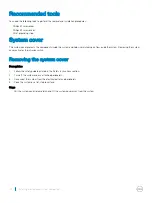
Pull the system cover release latch and lift the system cover away from the system

40

Installing and removing system components

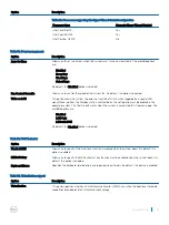
Summary of Contents for PowerEdge T30

Page 1: ...Dell PowerEdge T30 Owner s Manual Regulatory Model D13M Series Regulatory Type D13M002 ...

Page 2: ... to hardware or loss of data and tells you how to avoid the problem WARNING A WARNING indicates a potential for property damage personal injury or death 2016 11 Rev A00 Copyright 2016 Dell Inc or its subsidiaries All rights reserved Dell EMC and other trademarks are trademarks of Dell Inc or its subsidiaries Other trademarks may be trademarks of their respective owners ...

Page 3: ...ications 17 Chassis dimensions 17 Chassis weight 18 Processor specifications 18 PSU specifications 18 System battery specification 18 Expansion bus specifications 18 Memory specifications 18 Drive specifications 19 Hard drives 19 Optical drive 19 Ports and connectors specifications 19 USB ports 19 NIC port 20 Video specification 20 Environmental specifications 20 Particulate and gaseous contaminat...

Page 4: ...the system 44 Power switch 45 Removing the power switch 45 Installing the power switch 46 Chassis intrusion switch 47 Removing the chassis intrusion switch 47 Installing the chassis intrusion switch 48 Input Output I O panel 49 Removing the I O panel 49 Installing the I O panel 50 Hard drives 51 Removing the hard drive cage 52 Installing the hard drive cage 53 Removing a 3 5 inch hard drive carrie...

Page 5: ...stalling the power supply unit 84 System battery 85 Replacing the system battery 85 System board 86 Removing the system board 87 Installing the system board 88 Entering the system service tag using Intel Active Management Technology 89 Entering the system Service Tag by using System Setup 90 7 Using system diagnostics 91 Dell Embedded System Diagnostics 91 Running the Embedded System Diagnostics f...

Page 6: ...s 99 Power supply unit problems 100 Power supply unit Built in Self Test button 100 Troubleshooting cooling fans 101 Troubleshooting system memory 101 Troubleshooting an optical drive 102 Troubleshooting a hard drive 103 Troubleshooting expansion cards 103 Troubleshooting processors 104 10 Getting help 105 Contacting Dell 105 Documentation feedback 105 Accessing system information by using QRL 105...

Page 7: ...n kit and controller card Four DIMM slots supporting up to 64 GB of memory Three full height PCIe Gen 3 slots and one full height PCI slot One AC cabled power supply unit PSU Topics Supported configurations for the Dell PowerEdge T30 system Supported operating systems Front panel Back panel Diagnostic Indicators Supported configurations for the Dell PowerEdge T30 system The Dell PowerEdge T30 syst...

Page 8: ...only supports fixed configuration with no operating system preinstalled from the factory The configuration available in China offers Non ECC memory with no Windows operating system supported Table 1 Supported operating systems for T30 configuration Supported regions Configuration Supported Operating systems All regions 1 1x Processor Skylake Pentium G4400 1x 4 GB DIMM ECC 1x 1 TB Client hard drive...

Page 9: ... operating system OS on Dell PowerEdge Servers to ensure OS compatibility While most OS features work as expected on this platform some certification tests did not complete successfully These findings are documented at Dell com ostechsheets For more information on the specific versions and additions see the information on supported operating systems at dell com OSsupport Front panel The front pane...

Page 10: ...own an ACPI compliant operating system press the power button 2 Optical drive optional One optional slim SATA DVD ROM drive or DVD RW drive For information about the supported optical drive see the Technical specifications section 3 Microphone connector Use the Microphone connector to connect a microphone to the system 4 Headphone connector Use the Headphone connector to connect a headphone to the...

Page 11: ...e and the table describe the back panel features and indicators Figure 3 Back panel features and indicators Table 3 Back panel features and indicators Item Indicator Button or Connector Icon Description 1 AC power status indicator Indicates power activity 2 Self diagnostic button Indicates the health status of the power supply 3 Power connector Use the Power connector to connect the power cable 4 ...

Page 12: ...ctor to connect a serial device to the system 14 Ethernet port NIC One integrated 10 100 1000 Mbps Ethernet port Use this port to connect the system to the network 15 Security cable slot Allows you to connect a cable lock to the system 16 Padlock ring Allows you to lock the system cover Diagnostic Indicators The diagnostic indicators on the system indicate operation and error status Diagnostic ind...

Page 13: ...ondition A Link and activity indicators are off The NIC is not connected to the network B Link indicator is green The NIC is connected to a valid network at 10 Mbps or 100 Mbps port speed C Link indicator is orange The NIC is connected to a valid network at 1000 Mbps port speed D Activity indicator is flashing yellow Network data is being sent or received Power on LED indicator codes The Power on ...

Page 14: ...3 amber blinks followed by a short pause and then 5 amber blinks followed by long pause Then the pattern is repeated Table 7 Power on LED system diagnostics indicator codes Amber LED state Description 2 1 system board failure 2 2 system board PSU or PSU cabling failure 2 3 system board memory or CPU failure 2 4 coin cell battery failure 2 5 corrupt BIOS 2 6 CPU configuration failure or CPU failure...

Page 15: ...1 self diagnostic button 2 PSU status indicator Table 8 PSU status indicators Power indicator pattern Condition Green A valid power source is connected to the PSU and the PSU is operational Not lit Power is not connected Dell PowerEdge T30 system overview 15 ...

Page 16: ...hat is shipped with your system Dell com operatingsystemmanuals For information about installing the operating system see the operating system documentation Configuring your system For information about updating drivers and firmware see the Methods to download firmware and drivers section in this document Dell com support drivers Managing your system For information about upgrading your system Del...

Page 17: ...s of your system are outlined in this section Chassis dimensions Figure 6 Chassis dimensions of the PowerEdge T30 system Table 10 Dimensions of the PowerEdge T30 system X Y Z 175 00 mm 6 88 inches 360 00 mm 14 17 inches 454 00 mm 17 87 inches 3 Technical specifications 17 ...

Page 18: ...connect to the IT power systems with a phase to phase voltage not exceeding 230 V System battery specification The PowerEdge T30 system supports CR 2032 3 0 V lithium coin cell system battery Expansion bus specifications The PowerEdge T30 system supports PCI express PCIe generation 3 expansion cards which must be installed on the system board The following table provides detailed information about...

Page 19: ...rd drive internal cabled SATA or SATA SSD drives and two 2 5 inch hard drive optional internal cabled SATA or SATA SSD drives Three hard drives Up to three 3 5 inch hard drive internal cabled SATA or SATA SSD drives and one optical drive optional internal cabled SATA or SATA SSD drives Four hard drives Up to four 3 5 inch hard drive internal cabled SATA or SATA SSD drives NOTE If you install more ...

Page 20: ...em configurations see Dell com environmental_datasheets Table 17 Environmental specifications Type Condition Temperature or Specification Temperature Maximum Temperature Gradient Operating and Storage 20 C h 36 F h Storage Temperature Limits 40 C to 65 C 40 F to 149 F Continuous operation for altitude less than 950 m or 3117 ft 5 C to 35 C 41 F to 95 F with no direct sunlight on the equipment Rela...

Page 21: ...evels of particulates or gaseous pollution are beyond the limits specified in the following table and are the reason for the damage and or failures to your equipment it may be necessary for you to re mediate the environmental conditions that are causing the damage and or failures Re mediation of environmental conditions will be the responsibility of the customer Table 18 Particulate contamination ...

Page 22: ...Gaseous contamination Specifications Silver Coupon Corrosion Rate 200 Å month as defined by AHSRAE TC9 9 22 Technical specifications ...

Page 23: ...ell PowerEdge systems Supported Operating Systems for Dell PowerEdge Systems Methods to download firmware and drivers You can download the firmware and drivers from the Dell support site at Dell com support home Downloading the drivers and firmware Dell recommends that you download and install the latest BIOS and drivers on your system Prerequisites Ensure that you clear the web browser cache befo...

Page 24: ...d boot device order and boot directly to a specific device for example optical drive or hard drive During the Power on Self Test POST you can Access System Setup by pressing F2 Bring up the one time boot menu by pressing F12 The one time boot menu displays the devices that you can boot from including the diagnostic option The boot menu options are explained as follows Table 21 Boot Sequence Option...

Page 25: ...to the next field Enter Selects a value in the selected field if applicable or follow the link in the field Spacebar Expands or collapses a drop down list if applicable Tab Moves to the next focus area NOTE For the standard graphics browser only Esc Moves to the previous page until you view the main screen Pressing Esc in the main screen displays a message that prompts you to save any unsaved chan...

Page 26: ...option is enabled Date Time Allows you to set the date and time on the system The changes to the system date and time takes effect immediately Table 23 System configuration Option Description Integrated NIC Allows you to configure the integrated network controller The available options are Enable UEFI Network Stack Disabled NOTE You can use the Disabled option only if Active Management Technology ...

Page 27: ...e Front USB Ports Enable rear USB Ports Front USB Configuration Allows you to enable or disable the front USB ports The available options are Front Port 1 Front Port 2 Front Port 3 Front Port 4 Rear USB Configuration Allows you to enable or disable the rear USB ports The available options are Rear Port 1 Rear Port 2 Rear Port 3 Rear Port 4 Rear Port 5 Rear Port 6 USB PowerShare Allows you to enabl...

Page 28: ...able in the system The internal HDD_0 password enables several security features The available options are Enter the old password Enter the new password Confirm the new password By default the password is not set Strong Password Allows you to enable the option to always set strong passwords Strong Password is to Enable Strong Password By default this option is disabled Password Configuration Allow...

Page 29: ... options are Deactivate Disable Activate By default the Deactivate option is selected CPU XD Support Allows you to enable the Execute Disable mode of the processor By default CPU XD Support is set to Enable CPU XD Support OROM Keyboard Access Allows you to determine whether users are able to enter Option ROM Configuration screens using shortcut keys during boot The available options are Enable One...

Page 30: ...Intel SpeedStep Allows you to enable or disable the Intel SpeedStep feature Intel SpeedStep is set to Enable Intel SpeedStep C States Control Allows you to enable or disable the additional processor sleep states By default C States Control is set to C states Limit CPUID Value This field limits the maximum value the processor Standard CPUID Function supports Intel TurboBoost Allows you to enable or...

Page 31: ... unaffected by this setting and must be enabled in the operating system This feature only works when the system is connected to AC power supply The available options are Disabled LAN Only LAN with PXE By default the Disabled option is selected Table 31 POST behavior Option Description Numlock LED Allows you to specify if the NumLock function is enabled when the system boots By default this option ...

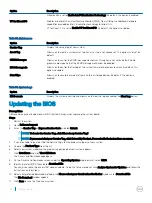
Page 32: ...t log and allows you to clear the log by enabling the Clear Log option Updating the BIOS Prerequisites Dell recommends you to update your BIOS System Setup when replacing the system board Steps 1 Restart the system 2 Go to Dell com support 3 Enter the Service Tag or Express Service Code and click Submit NOTE To locate the Service Tag click Where is my Service Tag NOTE If you cannot find your Servi...

Page 33: ...utton to shut down the system 5 Start the system 6 While the system is starting up press the Ctrl Esc keys while holding the power button until the BIOS Recovery Menu dialog box is displayed 7 Click Continue to start the BIOS recovery process NOTE Ensure that the Recovery BIOS option is selected in the BIOS Recovery Menu dialog box Trusted Platform Module specification The Dell PowerEdge T30 suppo...

Page 34: ...toProvisioning and press Enter Ensure that AutoProvisioning is enabled 15 To access the Trusted Platform Module Management on Local Computer in the Run window type tpm msc and click OK 16 In the Trusted Platform Module Management on Local Computer window ensure that the Specification Version 2 0is displayed in the TPM Manufacturer Information section 17 In the Actions pane click Prepare the TPM Th...

Page 35: ...iguring TPM Bitlocker key Prerequisites 1 Ensure that you have a supported Microsoft Windows Server Operating System installed on your system 2 Ensure that you have TPM version 2 0 installed on your system 3 Log in as an Administrator Steps 1 To access the Trusted Platform Module Management on Local Computer in the Run window type tpm msc and click OK 2 In the Trusted Platform Module Management on...

Page 36: ... Password and or Setup Password or change an existing System Password and or Setup Password only when Password Status is Unlocked If the Password Status is Locked you cannot change the System Password NOTE If the password jumper is disabled the existing System Password and Setup Password are deleted and you need not provide the system password to log on to the system About this task To enter the s...

Page 37: ...rm the deletion when promoted 5 Press Esc and a message prompts you to save the changes 6 Press Y to save the changes and exit from System Setup The system reboots Disabling a system password Prerequisites NOTE The system s software security features include a system password and a setup password The password jumper disables any password s currently in use 1 Follow the safety guidelines listed in ...

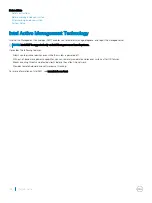
Page 38: ... AMT is supported only on Intel Xeon processor based systems It provides the following features Allows you to discover devices even while the system is powered off With out of band management capabilities you can remotely remediate and recover systems after OS failures Blocks incoming threats and infected clients before they affect the network Provides remote hardware and software asset tracking F...

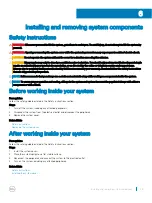
Page 39: ... you always use a static mat and static strap while working on components inside the system NOTE To ensure proper operation and cooling all bays in the system and system fans must be populated always with either a component or with a blank Before working inside your system Prerequisites Follow the safety guidelines listed in the Safety instructions section Steps 1 Turn off the system including any...

Page 40: ...e the system Removing the system cover activates the intrusion switch Removing the system cover Prerequisites 1 Follow the safety guidelines listed in the Safety instructions section 2 Turn off the system and any attached peripherals 3 Disconnect the system from the electrical outlet and peripherals 4 Place the system on a flat stable surface Steps Pull the system cover release latch and lift the ...

Page 41: ...ed links Safety instructions Installing the system cover Installing the system cover Prerequisites 1 Follow the safety guidelines listed in the Safety instructions section 2 Ensure that all internal cables are connected and placed out of the way and no tools or extra parts are left inside the system Steps 1 Align the tabs at the bottom of the system cover on the slots on the chassis 2 Push the sys...

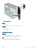
Page 42: ...d prevents accidents while removing the hard drive or when pressing the reset or power button The front bezel can also be locked for additional security Removing the bezel Prerequisites 1 Follow the safety guidelines listed in the Safety instructions section 2 Follow the procedure listed in the Before working inside your system section Steps 1 Release the four retention clips that secure the bezel...

Page 43: ...e bezel After working inside your system Installing the bezel Prerequisites 1 Follow the safety guidelines listed in the Safety instructions section 2 Follow the procedure listed in the Before working inside your system section Steps 1 Insert the bezel tabs into the bezel tab slots on the chassis 2 Press the bezel into the chassis until the retention clips lock into place Installing and removing s...

Page 44: ...ON Many repairs may only be done by a certified service technician You should only perform troubleshooting and simple repairs as authorized in your product documentation or as directed by the online or telephone service and support team Damage due to servicing that is not authorized by Dell is not covered by your warranty Read and follow the safety instructions that are shipped with your product 4...

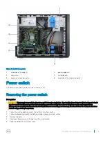
Page 45: ...imple repairs as authorized in your product documentation or as directed by the online or telephone service and support team Damage due to servicing that is not authorized by Dell is not covered by your warranty Read and follow the safety instructions that are shipped with your product 1 Follow the safety guidelines listed in the Safety instructions section 2 Follow the procedure listed in the Bef...

Page 46: ...pairs may only be done by a certified service technician You should only perform troubleshooting and simple repairs as authorized in your product documentation or as directed by the online or telephone service and support team Damage due to servicing that is not authorized by Dell is not covered by your warranty Read and follow the safety instructions that are shipped with your product 1 Follow th...

Page 47: ...cian You should only perform troubleshooting and simple repairs as authorized in your product documentation or as directed by the online or telephone service and support team Damage due to servicing that is not authorized by Dell is not covered by your warranty Read and follow the safety instructions that are shipped with your product 1 Follow the safety guidelines listed in the Safety instruction...

Page 48: ...leshooting and simple repairs as authorized in your product documentation or as directed by the online or telephone service and support team Damage due to servicing that is not authorized by Dell is not covered by your warranty Read and follow the safety instructions that are shipped with your product 1 Follow the safety guidelines listed in the Safety instructions section 2 Follow the procedure l...

Page 49: ...irected by the online or telephone service and support team Damage due to servicing that is not authorized by Dell is not covered by your warranty Read and follow the safety instructions that are shipped with your product 1 Follow the safety guidelines listed in the Safety instructions section 2 Follow the procedure listed in the Before working inside your system section 3 Remove the bezel 4 Keep ...

Page 50: ...rected by the online or telephone service and support team Damage due to servicing that is not authorized by Dell is not covered by your warranty Read and follow the safety instructions that are shipped with your product 1 Follow the safety guidelines listed in the Safety instructions section 2 Follow the procedure listed in the Before working inside your system section 3 Remove the bezel 4 Keep t...

Page 51: ...e the vertical type SATA cables to connect hard drives in the hard drive cage to avoid damaging the connector pins This is applicable for the 2 5 inch hard drives and optical drive NOTE Use right angle connectors to connect to the hard drives in the hard drive bay You may not be able to close the system cover if incorrect connector cables are used NOTE Do not mix enterprise class hard drives with ...

Page 52: ...ized by Dell is not covered by your warranty Read and follow the safety instructions that are shipped with your product 1 Follow the safety guidelines listed in the Safety instructions section 2 Follow the procedure listed in the Before working inside your system section 3 If applicable remove the power and data cables from the hard drives in the hard drive cage 4 Remove the bezel Steps Slide and ...

Page 53: ... the safety guidelines listed in the Safety instructions section 2 Follow the procedure listed in the Before working inside your system section Steps Insert the hard drive cage and push it into the system until it clicks into place Figure 19 Installing the hard drive cage Next steps 1 Install the bezel 2 If applicable connect the power and data cables to the hard drives and optical drive in the ha...

Page 54: ...Follow the procedure listed in the Before working inside your system section 3 If applicable disconnect the power and data cables from the hard drive in the hard drive cage 4 Remove the hard drive cage Steps Press the retention clips inwards and pull the hard drive out of the hard drive cage Figure 20 Removing a 3 5 inch hard drive carrier from the hard drive cage Next steps 1 Install the 3 5 inch...

Page 55: ...ve cage from the system NOTE If you have a 2 5 inch hard drive installed in the hard drive cage disconnect the power and data cables from the hard drive Steps 1 Align the ridges of the hard drive carrier with the grooves on the hard drive cage 2 Insert and push the hard drive into the hard drive cage until it clicks into place 3 Install the hard drive cage into the system Figure 21 Installing a 3 ...

Page 56: ...ow the safety instructions that are shipped with your product NOTE If you have an optical drive installed you cannot install the 2 5 inch hard drives until you remove the optical drive 1 Follow the safety guidelines listed in the Safety instructions section 2 Follow the procedure listed in the Before working inside your system section 3 If installed disconnect the cables connected to the 3 5 inch ...

Page 57: ... the power and data cables to the hard drive in the optical drive bay 2 Install a 2 5 inch hard drive in the optical drive bay 3 Follow the procedure listed in the After working inside your system section Related links Safety instructions Before working inside your system Removing the hard drive cage Installing a 2 5 inch hard drive s in the optical drive bay After working inside your system Insta...

Page 58: ...3 Remove the power and data cables from the hard drive in the hard drive cage Steps 1 Remove the hard drive cage from the system NOTE If you have a 3 5 inch hard drive seated in the hard drive cage a Remove the power and data cables from the hard drive b Remove the hard drive from the hard drive cage 2 Slide the hard drive into the optical drive bay 3 Tighten the screws on the sides of the hard dr...

Page 59: ...sert the hard drive cage into the system 2 Connect the power and data cables to the hard drive 3 Follow the procedure listed in the After working inside your system section 4 Reboot the system and press F2 to enter the System Setup and ensure that the hard drive controller is enabled Related links Safety instructions Before working inside your system Removing the hard drive cage Installing the har...

Page 60: ...drive from the hard drive bay Next steps 1 Install a 3 5 inch hard drive carrier from the hard drive bay 2 Follow the procedure listed in the After working inside your system section Related links Before working inside your system Installing a 3 5 inch hard drive carrier in the hard drive bay After working inside your system Installing a 3 5 inch hard drive carrier in the hard drive bay Prerequisi...

Page 61: ...em Removing a hard drive from a hard drive carrier Prerequisites CAUTION Many repairs may only be done by a certified service technician You should only perform troubleshooting and simple repairs as authorized in your product documentation or as directed by the online or telephone service and support team Damage due to servicing that is not authorized by Dell is not covered by your warranty Read a...

Page 62: ...nstalling a hard drive into a hard drive carrier Prerequisites CAUTION Many repairs may only be done by a certified service technician You should only perform troubleshooting and simple repairs as authorized in your product documentation or as directed by the online or telephone service and support team Damage due to servicing that is not authorized by Dell is not covered by your warranty Read and...

Page 63: ...arrier 1 pins 4 Next steps 1 Install the hard drive in the hard drive cage or hard drive bay 2 Connect the power and data cables to the hard drive 3 Follow the procedure listed in the After working inside your system section Related links Before working inside your system Installing a 3 5 inch hard drive carrier in the hard drive bay After working inside your system Installing and removing system ...

Page 64: ...structions that are shipped with your product 1 Follow the safety guidelines listed in the Safety instructions section 2 Follow the procedure listed in the Before working inside your system section 3 If applicable remove the power and data cables from the optical drive and hard drives in the hard drive cage 4 Remove the bezel 5 Remove the hard drive cage 6 Remove the screws securing the optical dr...

Page 65: ...ructions that are shipped with your product NOTE Only slim 9 5 mm SATA DVD ROM drive or DVD RW drive can be installed in your system External optical drives can be connected through USB ports NOTE If you install an optical drive you cannot install 2 5 inch hard drives NOTE To install more than four drive devices including optical drive and hard drives you need an additional power extension cable c...

Page 66: ...e optical drive filler Prerequisites CAUTION Many repairs may only be done by a certified service technician You should only perform troubleshooting and simple repairs as authorized in your product documentation or as directed by the online or telephone service and support team Damage due to servicing that is not authorized by Dell is not covered by your warranty Read and follow the safety instruc...

Page 67: ...e filler and remove the optical drive filler from the optical drive bay Figure 30 Removing the optical drive filler from the bezel Figure 31 Removing the optical drive filler from the optical drive bay Next steps 1 Install the hard drive cage 2 Install the bezel 3 Follow the procedure listed in the After working inside your system section Installing and removing system components 67 ...

Page 68: ... due to servicing that is not authorized by Dell is not covered by your warranty Read and follow the safety instructions that are shipped with your product 1 Follow the safety guidelines listed in the Safety instructions section 2 Follow the procedure listed in the Before working inside your system section 3 Remove the bezel 4 Remove the hard drive cage Steps 1 On the bezel press down on the reten...

Page 69: ...e risk of uncorrectable system error data loss and or silent data corruption Non ECC DIMM is not used for mission critical applications NOTE Non ECC DIMMs are supported only in selected countries for more information contact your sales representative System performance varies depending on Maximum frequency of the DIMMs Number of DIMMs populated per channel System profile selected for example Perfo...

Page 70: ...133 2400 Four 1 2 V NOTE MT s indicates DIMM speed in MegaTransfers per second General memory module installation guidelines Memory configurations that fail to observe these guidelines can prevent your system from booting stop responding during memory configuration or operating with reduced memory NOTE This system supports only UDIMMs The system supports Flexible Memory Configuration enabling the ...

Page 71: ...ollowing table shows sample memory configurations for a single processor configuration that follow the appropriate memory guidelines stated in this section CAUTION Dell recommends you to use ECC DIMMs to minimize the risk of uncorrectable system error data loss and or silent data corruption Non ECC DIMM is not used for mission critical applications NOTE 16 GB quad rank RDIMMs are not supported NOT...

Page 72: ...to servicing that is not authorized by Dell is not covered by your warranty Read and follow the safety instructions that are shipped with your product 1 Follow the safety guidelines listed in the Safety instructions section 2 Follow the procedure listed in the Before working inside your system section 3 Locate the appropriate memory module sockets Steps 1 To release the memory module from the sock...

Page 73: ...ule socket down and out to allow the memory module to be inserted into the socket CAUTION Handle each memory module only by the card edges ensuring not to touch the middle of the memory module or metallic contacts 2 Align the memory module s edge connector with the alignment key of the memory module socket and insert the memory module in the socket NOTE The memory module socket has an alignment ke...

Page 74: ...mentation or as directed by the online or telephone service and support team Damage due to servicing that is not authorized by Dell is not covered by your warranty Read and follow the safety instructions that are shipped with your product CAUTION Never operate your system with the system fan removed System can overheat and result in shutdown of the system and loss of data CAUTION Do not operate th...

Page 75: ... 5 minutes CAUTION Do not remove or install the system fan by holding the fan blades 1 Follow the safety guidelines listed in the Safety instructions section 2 Follow the procedure listed in the Before working inside your system section Steps 1 Hold the system fan by the sides with the cable end facing the bottom of the chassis 2 Align the four grommets of the system fan with the four grooves on t...

Page 76: ...cumentation or as directed by the online or telephone service and support team Damage due to servicing that is not authorized by Dell is not covered by your warranty Read and follow the safety instructions that are shipped with your product 1 Follow the safety guidelines listed in the Safety instructions section 2 Follow the procedure listed in the Before working inside your system section 3 Disco...

Page 77: ...he Before working inside your system section 3 Unpack the expansion card and prepare it for installation NOTE For instructions see the documentation accompanying the card Steps 1 Push out the expansion card release latch to open it 2 If installed remove the expansion card filler The steps for installing or removing an expansion card filler are similar to installing or removing an expansion card NO...

Page 78: ... Follow the procedure listed in the After working inside your system section Related links Before working inside your system After working inside your system Processors and heat sinks Use the following procedures when Removing and installing a heat sink Installing an additional processor Replacing a processor 78 Installing and removing system components ...

Page 79: ...the Phillips 2 screwdriver ready Steps 1 Loosen one of the screws that secure the heat sink to the system board Allow some time approximately 30 seconds for the heat sink to loosen from the processor 2 Remove the screw diagonally opposite to the screw that you first removed 3 Repeat step 1 and 2 for removing the remaining two screws 4 Lift the heat sink out of the system Figure 42 Removing a heat ...

Page 80: ...essure Be aware that the release lever can spring up suddenly if not firmly held Steps 1 Release the socket lever by pushing the lever down and out from under the tab on the processor shield 2 Lift the lever upward until the processor shield lifts CAUTION The processor socket pins are fragile and can be permanently damaged Be careful not to bend the pins in the processor socket when removing the p...

Page 81: ...Locate the processor socket 7 If applicable remove the socket protective cap WARNING The heat sink and processor are too hot to touch for some time after the system has been powered down Allow the heat sink and processor to cool down before handling them CAUTION Never remove the heat sink from a processor unless you intend to remove the processor The heat sink is necessary to maintain proper therm...

Page 82: ...Dell is not covered by your warranty Read and follow the safety instructions that are shipped with your product 1 Follow the safety guidelines listed in the Safety instructions section 2 Follow the procedure listed in the Before working inside your system section 3 Install the processor 4 If you are using an existing heat sink remove the thermal grease from the heat sink by using a clean lint free...

Page 83: ...certified service technician You should only perform troubleshooting and simple repairs as authorized in your product documentation or as directed by the online or telephone service and support team Damage due to servicing that is not authorized by Dell is not covered by your warranty Read and follow the safety instructions that are shipped with your product 1 Follow the safety guidelines listed i...

Page 84: ...ocumentation or as directed by the online or telephone service and support team Damage due to servicing that is not authorized by Dell is not covered by your warranty Read and follow the safety instructions that are shipped with your product 1 Follow the safety guidelines listed in the Safety instructions section 2 Follow the procedure listed in the Before working inside your system section Steps ...

Page 85: ...hipped with your system CAUTION Many repairs may only be done by a certified service technician You should only perform troubleshooting and simple repairs as authorized in your product documentation or as directed by the online or telephone service and support team Damage due to servicing that is not authorized by Dell is not covered by your warranty Read and follow the safety instructions that ar...

Page 86: ...inside your system section 2 Press F2 to enter the System Setup to confirm that the battery is operating properly 3 Enter the correct time and date in the System Setup Time and Date fields 4 Exit System Setup System board A system board also known as the motherboard is the main printed circuit board found in systems The system board allows communication between many of the crucial electronic compo...

Page 87: ...ccess the encrypted data on your hard drives 1 Follow the safety guidelines listed in the Safety instructions section 2 Follow the procedure listed in the Before working inside your system section 3 Remove the following a system fan b all expansion cards WARNING The heat sink and processor are too hot to touch for some time after the system has been powered down Allow the heat sink and processor t...

Page 88: ... the Trusted Program Module TPM with an encryption key you may be prompted to create a recovery key during program or system setup Be sure to create and safely store this recovery key If you replace this system board you must supply the recovery key when you restart your system or program before you can access the encrypted data on your hard drives 1 Follow the safety guidelines listed in the Safe...

Page 89: ...Service Tag After Replacing The System Board section Related links Before working inside your system Installing a heat sink Installing a processor Installing a memory module Installing an expansion card Installing the system fan After working inside your system Entering the system service tag using Intel Active Management Technology Prerequisites NOTE Intel Active Management Technology AMT is supp...

Page 90: ...nformation in the Enter Service Tag section 7 Type the optional asset tag information in the Enter Asset Tag section 8 Click OK to save the changes and exit NOTE MANAGEABILITY ENGINE ME LOCKOUT is not supported for the PowerEdge T30 Entering the system Service Tag by using System Setup 1 Turn on the system 2 Press F2 to enter System Setup 3 Click Service Tag Settings 4 Enter the Service Tag NOTE Y...

Page 91: ...on about the failed device s View status messages that inform you if tests are completed successfully View error messages that inform you of problems encountered during testing Running the Embedded System Diagnostics from Boot Manager Prerequisites Run the Embedded System Diagnostics ePSA if your system does not boot Steps 1 When the system is booting press F11 2 Use the up arrow and down arrow ke...

Page 92: ...ectors on the various boards in the system Jumpers on the system board help to disable system and setup passwords You must know the connectors on the system board to install components and cables correctly Topics System board connectors System board jumper settings Disabling forgotten password System board connectors Figure 52 System board connectors 8 92 Jumpers and connectors ...

Page 93: ...RUDER intrusion switch connector 12 ATX_CPU P2 power connector 13 FAN_SYS System fan connector 14 CPU CPU socket 15 FAN_CPU CPU fan connector 16 BATTERY coin cell battery 17 DIMM slots Memory slot 18 F_PANEL1 front power switch connector 19 ATX_SYS_1 8 pin power connector 20 SATA1 SATA 1 connector 21 SATA2 SATA 2 connector 22 SATA_PWR HDD_ODD_Power cable connector 23 F_USB4 USB 3 0 connector 24 SA...

Page 94: ...tached peripherals and disconnect the system from the electrical outlet 2 Remove the system cover 3 Move the jumper on the system board jumper from pins 4 and 6 to pins 2 and 4 4 Install the system cover The existing passwords are not disabled erased until the system boots with the jumper on pins 2 and 4 However before you assign a new system and or setup password you must move the jumper back to ...

Page 95: ...nimum to POST Troubleshooting system startup failure Troubleshooting external connections Troubleshooting the video subsystem Troubleshooting a USB device Troubleshooting a serial I O device Troubleshooting a NIC Troubleshooting a wet system Troubleshooting a damaged system Troubleshooting the system battery Troubleshooting power supply units Troubleshooting cooling fans Troubleshooting system mem...

Page 96: ...d reconnect them 2 If the problem persists connect the keyboard and or mouse to another USB port on the system 3 If the problem is resolved restart the system enter System Setup and check if the non functioning USB ports are enabled NOTE Older operating systems may not support USB 3 0 4 If the problem is not resolved replace the keyboard and or mouse with a known working keyboard or mouse If the p...

Page 97: ...ry another known good network cable If the problem persists use another connector on the switch or hub 4 Ensure that the appropriate drivers are installed and the protocols are bound For more information see the NIC documentation 5 Enter System Setup and confirm that the NIC ports are enabled on the Integrated Devices screen 6 Ensure that all the NICs hubs and switches on the network are set to th...

Page 98: ...Using system diagnostics Getting help Removing the system cover Installing the system cover Troubleshooting a damaged system Prerequisites CAUTION Many repairs may only be done by a certified service technician You should only perform troubleshooting and simple repairs as authorized in your product documentation or as directed by the online or telephone service and support team Damage due to servi...

Page 99: ...t and turn on the system 4 Enter System Setup If the date and time displayed in System Setup are not correct check the System Error Log SEL for system battery messages Next steps If the problem persists see the Getting help section Related links System Setup Getting help Troubleshooting power supply units CAUTION Many repairs may only be done by a certified service technician You should only perfo...

Page 100: ...not turn on further troubleshooting is required to determine the point of failure Open the system and disconnect the power cables from all devices including the system board and press the PSU BIST button Option Description If the LED turns green this indicates that the PSU is functioning properly Further troubleshooting is required to determine the point of failure Attach the power cable s to the ...

Page 101: ...ed by the online or telephone service and support team Damage due to servicing that is not authorized by Dell is not covered by your warranty Read and follow the safety instructions that are shipped with your product Steps 1 If the system is operational run the appropriate system diagnostic test See the Using system diagnostics section for the available diagnostic tests If the diagnostic tests ind...

Page 102: ...tem cover Troubleshooting an optical drive Prerequisites CAUTION Many repairs may only be done by a certified service technician You should only perform troubleshooting and simple repairs as authorized in your product documentation or as directed by the online or telephone service and support team Damage due to servicing that is not authorized by Dell is not covered by your warranty Read and follo...

Page 103: ...ified service technician You should only perform troubleshooting and simple repairs as authorized in your product documentation or as directed by the online or telephone service and support team Damage due to servicing that is not authorized by Dell is not covered by your warranty Read and follow the safety instructions that are shipped with your product NOTE When troubleshooting an expansion card...

Page 104: ...amage due to servicing that is not authorized by Dell is not covered by your warranty Read and follow the safety instructions that are shipped with your product Steps 1 Run the appropriate diagnostics test See the Using system diagnostics section 2 Turn off the system and attached peripherals and disconnect the system from the electrical outlet 3 Remove the system cover 4 Ensure that the processor...

Page 105: ...t category b Select your product segment c Select your product The support page that lists the various support categories is displayed 5 For contact details of Dell Global Technical Support a Click Global Technical Support b The Contact Technical Support page is displayed with details to call chat or e mail the Dell Global Technical Support team Documentation feedback You can rate the documentatio...

Page 106: ...ne by visiting dell com QRL or by using your smartphone or tablet and a model specific Quick Resource QR code located on your Dell PowerEdge system To try out the QR code scan the following image Figure 53 Quick resource locator Locating Service Tag of your system Your system is identified by a unique Express Service Code and Service Tag number The Express Service Tag is found on top of the system...

Page 107: ...Figure 54 Locating Service Tag of your system Getting help 107 ...

Reviews: