background image

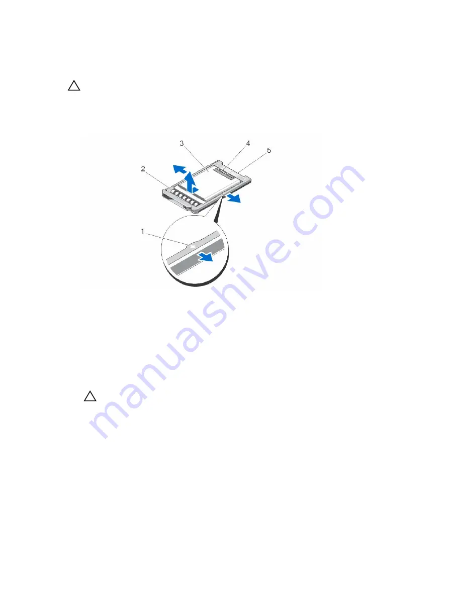
Removing a 1.8 inch SSD from the SSD carrier

CAUTION: To avoid damaging the SSD or the SSD carrier, do not use excessive force while 
removing the SSD from the SSD carrier.

1.

Pull outward on the edges of the SSD carrier in the direction of the arrows marked on the SSD carrier 
and disengage the SSD from the carrier.

2.

Slide the SSD out of the SSD carrier.

Figure 24. Removing and installing a 1.8 inch SSD into an SSD carrier

1.

arrows (2)

2. SSD carrier

3. SSD

4. SSD connectors

5. connector alignment label

Installing a 1.8 inch SSD in the SSD carrier

1.

Align the SSD with the SSD carrier so that the connectors on the SSD face up and match the 

connector alignment label on the SSD carrier.

CAUTION: To avoid damaging the SSD or the SSD carrier, do not use excessive force while 
installing the SSD in the SSD carrier.

2.

Slide the SSD into the SSD carrier until it is secured inside the SSD carrier.

Hard-drive/SSD backplane

The 2.5 inch hard-drive/SSD system supports one hard-drive/SSD backplane. The following procedure is 
applicable to the 2.5 inch hard-drive/SSD configuration.

48

Summary of Contents for PowerEdge E02B

Page 1: ...Dell PowerEdge FM120x4 Owner s Manual Regulatory Model E02B Regulatory Type E02B002 ...

Page 2: ...problem WARNING A WARNING indicates a potential for property damage personal injury or death Copyright 2015 Dell Inc All rights reserved This product is protected by U S and international copyright and intellectual property laws Dell and the Dell logo are trademarks of Dell Inc in the United States and or other jurisdictions All other marks and names mentioned herein may be trademarks of their res...

Page 3: ...Managing your system remotely 15 Downloading drivers and firmware 15 3 Pre operating system management applications 16 Navigation keys 16 About system setup 17 Entering System Setup 17 System Setup main screen 17 System BIOS screen 17 System Information screen 18 Memory Settings screen 18 Processor Settings screen 19 SATA Settings screen 19 Boot Settings screen 19 Integrated Devices screen 20 Seri...

Page 4: ...tools 33 Removing the sled 33 Installing the sled 34 Inside the sled 35 Cable cover 36 Removing the cable cover 36 Installing the cable cover 37 Cooling shroud 38 Removing the cooling shroud 38 Installing the cooling shroud 39 System memory 39 General memory module installation guidelines 40 Sample memory configurations 41 Removing memory modules 41 Installing memory modules 42 Hard drives SSDs 44...

Page 5: ...em 59 Safety first for you and your system 59 Troubleshooting system memory 59 Troubleshooting hard drives 60 Troubleshooting USB devices 60 Troubleshooting the system board 61 Troubleshooting the system battery 61 System messages 62 Warning messages 62 Diagnostic messages 62 Alert messages 62 6 Using system diagnostics 63 Dell Embedded System Diagnostics 63 When to use the Embedded System Diagnos...

Page 6: ...e specifications 68 Connectors specifications 69 Video specifications 69 Battery specifications 69 Expanded operating temperature 69 Environmental specifications 70 9 Getting help 73 Contacting Dell 73 Accessing system information by using QRL 73 Locating your system Service Tag 74 6 ...

Page 7: ...e FX2 enclosure Sled or system Refers to the PowerEdge FM120x4 system Nodes Refer to the four compute nodes Intel Atom C2000 processors in the FM120x4 sled Each node functions as an independent server and can be remotely managed through individual iDRACs Hard drive SSD bay Refers to the slots on the sled front panel in which the hard drives SSDs are installed Warm swap A component is considered wa...

Page 8: ...h hard drive SSD system Figure 2 Front panel features and indicators 1 8 inch SSD system Table 2 Front panel features and indicators Item Indicator Button or Connector Icon Description 1 Hard drives SSDs 2 5 inch hard drive SSD system Four 2 5 inch warm swap SATA hard drives or SATA SSDs 8 ...

Page 9: ...lar node in the sled 5 USB connector Allows a USB device to be connected to the system 6 Sled handle Used to slide the sled out of the enclosure Hard drive SSD indicator patterns The hard drive SSD indicators display different patterns as drive events occur in the system NOTE The sled must have a hard drive SSD or a hard drive SSD blank installed in each drive bay Figure 3 Hard drive SSD indicator...

Page 10: ... is applied Drives are not ready for insertion or removal during this time Blinks green amber and turns off Drive predicted failure Blinks amber four times per second Drive failed Blinks green slowly Drive rebuilding Steady green Drive online Blinks green three seconds amber three seconds and turns off six seconds Rebuild aborted Node status indicators Figure 4 Node status indicators 1 node A stat...

Page 11: ...e front which allows you to connect a USB diskette drive USB DVD CD drive keyboard or mouse The sled USB port is shared between the four nodes in the system The USB drives can be used to configure the sled NOTE Your sled supports only Dell branded USB 2 0 drives NOTE To designate the drive as the boot drive connect the USB drive restart the system then enter the System Setup and set the drive as f...

Page 12: ...unch enable and disable Dell Lifecycle Controller know the features use and troubleshoot Dell Lifecycle Controller Dell Lifecycle Controller User s Guide at Dell com idracmanuals Use Dell Lifecycle Controller Remote Services Dell Lifecycle Controller Remote Services Quick Start Guide at Dell com idracmanuals Set up use and troubleshoot OpenManage Server Administrator Dell OpenManage Server Adminis...

Page 13: ...tem service tag to quickly access your specific hardware configuration and warranty information A direct link to Dell to contact technical support and sales teams 1 Go to Dell com QRL and navigate to your specific product or 2 Use your smartphone or tablet to scan the model specific Quick Resource QR code located in the following image or on your Dell PowerEdge system 13 ...

Page 14: ...s the power button 5 Turn on the sled by pressing the power button on the sled Alternatively you can also turn on the sled by using The sled iDRAC For more information see Logging in to iDRAC The enclosure Chassis Management Controller CMC after the sled iDRAC is configured on the CMC For more information see the CMC User s Guide at Dell com esmmanuals Setting up and configuring the iDRAC IP addre...

Page 15: ...om ossupport Managing your system remotely To perform out of band systems management by using iDRAC you must configure iDRAC for remote accessibility set up the management station and managed system and configure the supported Web browsers For more information see the iDRAC User s Guide at Dell com esmmanuals You can also remotely monitor and manage the sleds from a single workstation using the De...

Page 16: ...Controller F11 Enables you to enter Boot Manager F12 Enables you to enter PXE Boot Page Up Enables you to move to the previous screen Page Down Enables you to move to the next screen Up arrow Enables you to move to the previous field Down arrow Enables you to move to the next field Enter Enables you to type a value in the selected field if applicable Spacebar Enables you to expand or collapse a dr...

Page 17: ...ult settings Menu Item Description System BIOS This option is used to view and configure BIOS settings iDRAC Settings This option is used to view and configure iDRAC settings Device Settings This option is used to view and configure device settings System BIOS screen NOTE The options for System Setup change based on the system configuration NOTE System Setup defaults are listed under their respect...

Page 18: ...ystem Miscellaneous Settings Displays options to change the system date time and so on System Information screen Menu Item Description System Model Name Displays the system model name System BIOS Version Displays the BIOS version installed on the system System Service Tag Displays the system Service Tag System Manufacturer Displays the name of system manufacturer System Manufacturer Contact Inform...

Page 19: ...ormation see Processor Core Licensing Processor 64 bit Support Specifies if the processor s support 64 bit extensions Processor Core Speed Displays the maximum core frequency of the processor Processor X Family Model Stepping Displays the family and model number of each processor A submenu displays the brand name core speed the amount of cache memory and the number of cores of the processor s SATA...

Page 20: ...ws you to set the user accessible ports Selecting All Ports Off disables all USB ports By default the User Accessible USB Ports option is set to All Ports On Embedded NIC1 and NIC2 Allows you to enable or disable the Operating System interface of the embedded NIC1 and NIC2 controller By default the Embedded NIC1 and NIC2 option is set to Enabled OS Watchdog Timer Allows you to enable or disable th...

Page 21: ...System DBPM DAPC DBPM is Demand Based Power Management Memory Frequency Allows you to set the memory frequency By default the Memory Frequency option is set to Maximum Performance Turbo Boost Allows you to enable or disable the processor to operate in turbo boost mode By default the Turbo Boost option is set to Enabled C States Allows you to enable or disable the processor to operate in all availa...

Page 22: ... Status Allows you to lock the system password By default the Password Status option is set to Unlocked AC Power Recovery Allows you to set how the system reacts after AC power is restored to the system By default the AC Power Recovery option is set to Last Miscellaneous Settings screen Menu Item Description System Time Allows you to set the time on the system System Date Allows you to set the dat...

Page 23: ...Menu Item Description Continue Normal Boot The system attempts to boot to devices starting with the first item in the boot order If the boot attempt fails the system continues with the next item in the boot order until the boot is successful or no more boot options are found BIOS Boot Menu Displays the list of available BIOS boot options marked with asterisks Select the boot option you wish to use...

Page 24: ...it Choosing the system boot mode System Setup enables you to specify the boot mode for installing your operating system BIOS boot mode the default is the standard BIOS level boot interface UEFI boot mode is an enhanced 64 bit boot interface based on Unified Extensible Firmware Interface UEFI specifications that overlays the system BIOS You must select the boot mode in the Boot Mode field of the Bo...

Page 25: ... 9 Only lower case letters are valid upper case letters are not allowed The following special characters are allowed space A message prompts you to reenter the system password 6 Reenter the system password that you entered earlier and click OK 7 Select Setup Password enter your system password and press Enter or Tab A message prompts you to re enter the setup password 8 Reenter the setup password ...

Page 26: ...sword and press Enter or Tab NOTE If you change the System and or Setup password a message prompts you to re enter the new password If you delete the System and or Setup password a message prompts you to confirm the deletion 7 Press Esc to save the changes NOTE You can disable password security while logging on to the system To disable the password security turn on or reboot your system type your ...

Page 27: ... Some of the features mentioned in the list may require the iDRAC 7 Enterprise License upgrade Configure enable or disable the iDRAC local area network through the dedicated iDRAC Enterprise card port or the embedded NIC Enable or disable IPMI over LAN Enable a LAN Platform Event Trap PET destination Attach or detach the Virtual Media devices For more information on using iDRAC7 see the iDRAC7 Use...

Page 28: ...edgemanuals There are four networking configurations supported on the FM120x4 system You can select the network configuration from the CMC web interface All FM120x4 sleds in the FX2 enclosure have the same network configuration For more information on the networking configurations supported on your system see Dell com poweredgemanuals Standard configuration In this configuration the uplink ports f...

Page 29: ...e external rack switches are on the same network in this configuration NOTE The network adapter isolation configuration also supports uplinks of all four ports to a single external rack switch This configuration enhances security as security features like firewalls are installed in the external rack switches and is useful in multi tenant configurations Figure 6 Network adapter isolation configurat...

Page 30: ...re isolated from other nodes in the sled with a dedicated IOM port mapped to LAN on motherboard LOM on each nodes The LOM1 on each node is operational and it is recommended that the LOM2 must be disabled in the operating system This configuration functions when the TOR connections for each node within a sled are on the network layer 2 domain This configuration enhances security as security feature...

Page 31: ...ch of the four nodes on an FM120x4 system is mapped to a single port on the I O module The network traffic from the nodes in the compute sled to the I O modules in the enclosure is routed through a network switch that is embedded on the compute sled system board Figure 9 Node to I O module port mapping for the enhanced network isolation configuration Table 9 I O module port mapping FM120x4 FM120x4...

Page 32: ...FM120x4 IO Module A1 Top IO Module A2 Bottom 3 3a 2b 3c 3d 4 4a 4b 4c 4d 32 ...

Page 33: ...mage due to servicing that is not authorized by Dell is not covered by your warranty Read and follow the safety instructions that came with the product Removing the sled 1 Turn off the nodes using the operating system commands or the iDRAC or the CMC The sled is powered off when all the nodes are turned off When the sled power is off its front panel power indicator is off 2 Turn off the sled using...

Page 34: ...cover from the I O connectors and save for future use 2 Align the sled with the sled bay on the enclosure and slide the sled into the enclosure until the sled connectors engage with the enclosure midplane The sled handle rotates toward the enclosure as the sled slides into the enclosure 3 Press the sled handle to closed position until the release button clicks into place 4 Turn on the sled 34 ...

Page 35: ...de the sled Figure 11 Inside the sled 2 5 inch hard drive SSD system 1 system board 2 cooling shroud 3 cable cover 4 SATA cables 2 5 DIMMs 8 6 hard drive SSD backplane 7 hard drives SSDs 4 8 sled handle 35 ...

Page 36: ...rvice and support team Damage due to servicing that is not authorized by Dell is not covered by your warranty Read and follow the safety instructions that came with the product 1 Turn off the nodes using the operating system commands or the iDRAC or the CMC The sled is powered off when all the nodes are turned off 2 Remove the sled from the enclosure 3 Press the release latch on the cooling shroud...

Page 37: ...upport team Damage due to servicing that is not authorized by Dell is not covered by your warranty Read and follow the safety instructions that came with the product 1 Align the tabs on the cable cover with the slots on the cooling shroud NOTE Ensure that the cables are routed properly on the cooling shroud before installing the cable cover 2 Lower the cable cover on to the cooling shroud until th...

Page 38: ...ckly resulting in shutdown of the system and loss of data 1 Turn off the nodes using the operating system commands or the iDRAC or the CMC The sled is powered off when all the nodes are turned off 2 Remove the sled from the enclosure 3 Remove the cable cover from the cooling shroud 4 Disconnect the SATA cables from the connectors on the system board NOTE Note the routing of the SATA cables on the ...

Page 39: ... the cooling shroud 5 Install the sled in the enclosure 6 Turn on the sled System memory Your system supports unregistered ECC DIMMs ECC UDIMMs It supports 1 35 V DDR3L voltage specifications The memory bus operating frequency is 1600 MT s NOTE MT s indicates DIMM speed in MegaTransfers per second The following table shows the memory populations and operating frequencies for the supported configur...

Page 40: ...Your system supports Flexible Memory Configuration enabling the system to be configured and run in any valid chipset architectural configuration The following are the recommended guidelines for optimal performance Memory modules must be of the same type and capacity for all the nodes At least one memory module must be populated for each node The memory configuration for each node must be identical...

Page 41: ... time after the system has been powered down Allow the memory modules to cool before handling them Handle the memory modules by the card edges and avoid touching the components or metallic contacts on the memory module CAUTION Many repairs may only be done by a certified service technician You should only perform troubleshooting and simple repairs as authorized in your product documentation or as ...

Page 42: ... the system has been powered down Allow the memory modules to cool before handling them Handle the memory modules by the card edges and avoid touching the components or metallic contacts on the memory module CAUTION Many repairs may only be done by a certified service technician You should only perform troubleshooting and simple repairs as authorized in your product documentation or as directed by...

Page 43: ...e to the center of the memory module 6 Press down on the memory module with your thumbs to lock the memory module into the socket Figure 18 Installing the memory module 1 memory module 2 memory module ejectors 3 memory module socket alignment key 4 memory module alignment key NOTE When the memory module is properly seated in the socket the ejectors on the memory module socket align with the ejecto...

Page 44: ... shared resources between the nodes in the system Each hard drive SSD is assigned to a specific node Depending on the configuration the hard drives SSDs are assigned to the nodes in the following order Figure 19 Hard drive SSD bay numbering 2 5 inch hard drive SSD system Table 12 Hard drive SSD to node assignment 2 5 inch hard drive SSD configuration Hard Drive SSD Bay Node A 0 A B 0 B C 0 C D 0 D...

Page 45: ...ating system 1 To remove a 2 5 inch hard drive SSD turn off the node to which the hard drive is assigned using the iDRAC 2 Take the hard drive SSD offline and wait until the hard drive SSD indicators on the drive carrier are off The drive is ready for removal NOTE See your operating system documentation for more information on taking the drive offline 3 Open the hard drive SSD carrier handle to re...

Page 46: ... is assigned to a specific node and the node to which it is assigned must be turned off before servicing the hard drive SSD 1 Open the hard drive SSD carrier handle 2 Insert the hard drive SSD carrier into the drive bay Carefully align the channel on the hard drive SSD carrier with the appropriate drive slot on the sled 3 Push the drive carrier into the drive bay 4 Rotate the carrier handle to the...

Page 47: ...SD carrier 2 Lift the hard drive SSD out of the hard drive SSD carrier Figure 23 Removing and installing a 2 5 inch hard drive SSD in a hard drive SSD carrier 1 hard drive SSD 2 screw holes 4 3 hard drive SSD carrier 4 screws 4 Installing a 2 5 inch hard drive SSD in a hard drive SSD carrier 1 Insert the hard drive SSD into the hard drive SSD carrier with the connector end of the drive at the back...

Page 48: ... SSD carrier 3 SSD 4 SSD connectors 5 connector alignment label Installing a 1 8 inch SSD in the SSD carrier 1 Align the SSD with the SSD carrier so that the connectors on the SSD face up and match the connector alignment label on the SSD carrier CAUTION To avoid damaging the SSD or the SSD carrier do not use excessive force while installing the SSD in the SSD carrier 2 Slide the SSD into the SSD ...

Page 49: ...the nodes are turned off 2 Remove the sled from the enclosure CAUTION Note the number of each hard drive SSD and temporarily label them before removal so that you can replace them in the same locations CAUTION To prevent damage to the hard drives SSDs and the hard drive SSD backplane remove the hard drives SSDs from the sled before removing the hard drive SSD backplane 3 Remove the hard drive s SS...

Page 50: ...e assembly CAUTION Many repairs may only be done by a certified service technician You should only perform troubleshooting and simple repairs as authorized in your product documentation or as directed by the online or telephone service and support team Damage due to servicing that is not authorized by Dell is not covered by your warranty Read and follow the safety instructions that came with the p...

Page 51: ...y seated and the spring loaded screw on the cage aligns with the screw hole on the chassis 3 Tighten the spring loaded screw to secure the SSD cage assembly to the chassis 4 Connect the SATA and power cables to the SSD backplane connectors 5 Install the SSDs 6 Install the sled in the enclosure 7 Turn on the sled Easy restore module If you do not have a system service tag after system board replace...

Page 52: ...re is a danger of a new battery exploding if it is incorrectly installed Replace the battery only with the same or equivalent type recommended by the manufacturer Discard used batteries according to the manufacturer s instructions See the safety instructions that came with your system for additional information CAUTION Many repairs may only be done by a certified service technician You should only...

Page 53: ...oud 10 Install the cable cover 11 Install the sled in the enclosure 12 Turn on the sled 13 Enter the System Setup to confirm that the battery is operating properly 14 Enter the correct time and date in the System Setup Time and Date fields 15 Exit the System Setup 16 Repeat steps 14 to 16 for each node 17 To test the newly installed battery remove the sled for at least an hour 18 After an hour rei...

Page 54: ... board WARNING The processor and heat sink can become extremely hot Be sure the processor has had sufficient time to cool before handling WARNING The memory modules are hot to the touch for some time after the system has been powered down Allow time for the memory modules to cool before handling them Handle the memory modules by the card edges and avoid touching the components NOTE If you are remo...

Page 55: ...r warranty Read and follow the safety instructions that came with the product CAUTION Exercise care when removing and installing the system board in the sled to prevent any damage to the system board 1 Unpack the new system board assembly 2 Position the system board so that the I O connectors on the system board are toward the back of the system 3 Align the screw holes on the system board with the...

Page 56: ...tings After the restore process is complete the system restarts Control panel Removing the control panel CAUTION Many repairs may only be done by a certified service technician You should only perform troubleshooting and simple repairs as authorized in your product documentation or as directed by the online or telephone service and support team Damage due to servicing that is not authorized by Del...

Page 57: ... that came with the product 1 Align the screw holes on the control panel board with the screw holes on the control panel bracket 2 Install the three screws to secure the control panel board to the control panel bracket 3 Connect the control panel cable to the connector on the control panel board 4 Position the control panel assembly so that the USB connector and USB select button face the front of...

Page 58: ...b hard drive SSD backplane c cooling shroud d cable cover e memory modules f hard drives SSDs 8 Install the sled in the enclosure 9 Turn on the sled 58 ...

Page 59: ...ot covered by your warranty Read and follow the safety instructions that came with the product NOTE Before performing the following procedure ensure that you have installed the memory modules according to the memory module installation guidelines for the sled 1 Restart the sled a Turn off the nodes using the operating system commands or the iDRAC b Press the power button once to turn off the sled ...

Page 60: ...rive and install it in the other drive bay 6 If the problem is resolved reinstall the hard drive in the original bay If the hard drive functions properly in the original bay the drive carrier could have intermittent problems Replace the drive carrier 7 If the hard drive is the boot drive ensure that the drive is configured and connected properly 8 Partition and logically format the hard drive 9 If...

Page 61: ...afety instructions that came with the product The battery maintains the sled configuration date and time information in the NVRAM when the sled is turned off You may need to replace the battery if an incorrect time or date is displayed during the boot routine You can operate the sled without a battery however the sled configuration information maintained by the battery in NVRAM is erased each time...

Page 62: ... the task and require you to respond by typing y yes or n no NOTE Warning messages are generated by either the application or the operating system For more information see the documentation that accompanied the operating system or application Diagnostic messages The system diagnostic utilities may issue messages if you run diagnostic tests on your system For more information about system diagnosti...

Page 63: ...status messages that inform you if tests are completed successfully View error messages that inform you of problems encountered during testing When to use the Embedded System Diagnostics Run the Embedded System Diagnostics ePSA if your system does not boot Running the Embedded System Diagnostics The embedded system diagnostics program is run from the Dell Lifecycle Controller CAUTION Use the embed...

Page 64: ...ed select the media to perform a one time boot If diagnostics does not start automatically after the diagnostics media is booted enter psa at the command prompt System diagnostics controls Menu Description Configuration Displays the configuration and status of all detected devices Results Displays the results of all tests that are executed System health Provides the current overview of the system ...

Page 65: ... separate configuration jumpers To locate the jumpers for each node see System Board Connectors For information on resetting the password jumper to disable a password see Disabling A Forgotten Password Table 14 System board jumper settings Jumper Setting Description NVRAM_CLR default The configuration settings are retained at system boot The configuration settings are cleared at the next system bo...

Page 66: ...V coin cell battery 5 J_FRU Easy Restore Module connector 6 A CPU and heat sink for Node A 7 A_A1 A_A2 Memory module sockets for node A 8 J_PW_NVRAM1 System configuration jumpers for node A 9 J_BLADE Sled connectors to the enclosure midplane 10 B_A1 B_A2 Memory module sockets for node B 11 J_PW_NVRAM3 System configuration jumpers for node B 12 B CPU and heat sink for Node B 13 SATA_A SATA connecto...

Page 67: ...hen all the nodes are turned off 2 Remove the sled from the enclosure 3 Locate the jumpers on the system board 4 Relocate the jumper plug to disable the password feature 5 Install the sled in the enclosure 6 Turn on the sled When the sled is on the power on indicator is solid green The nodes also power on when the sled is turned on and the node indicators are solid blue Allow the sled to finish bo...

Page 68: ... Four Intel Atom processor C2000 product family Memory specifications Memory Specifications Architecture 1600 MT s DDR3 DIMMs Memory module sockets Eight 240 pin Memory module capacities UDIMMs 4 GB single rank and 8 GB dual rank Minimum RAM 16 GB Maximum RAM 64GB Drive specifications Drives Specifications Hard drives Four 2 5 inch warm swap SATA hard drives SSDs Four 2 5 inch warm swap SATA SSDs ...

Page 69: ...e impacted NOTE When operating in the expanded temperature range ambient temperature warnings may be reported in the System Event Log Expanded operating temperature Specifications 10 of annual operating hours 5 C to 10 C 41 F to 50 F and 35 C to 40 C 95 F to 104 F at 5 to 85 RH with 29 C 84 2 F dew point NOTE Outside the standard operating temperature 10 C to 35 C the system can operate down to 5 ...

Page 70: ...nal information about environmental measurements for specific system configurations see Dell com environmental_datasheets Temperature Specifications Maximum Temperature Gradient Operating and Storage 20 C h 36 F h Storage Temperature Limits 40 C to 65 C 40 F to 149 F Temperature Continuous Operation Specifications Temperature Ranges for altitude less than 950 m or 3117 ft 10 C to 40 C 50 F to 104 ...

Page 71: ...T equipment damage and or failure from particulates and gaseous contamination If it is determined that levels of particulates or gaseous pollution are beyond the limits specified below and are the reason for the damage and or failures to your equipment it may be necessary for you to re mediate the environmental conditions that are causing the damage and or failures Re mediation of environmental co...

Page 72: ...ity NOTE Applies to data center and non data center environments Gaseous Contamination Specifications Copper Coupon Corrosion Rate 300 Å month per Class G1 as defined by ANSI ISA71 04 1985 Silver Coupon Corrosion Rate 200 Å month as defined by AHSRAE TC9 9 NOTE Maximum corrosive contaminant levels measured at 50 relative humidity 72 ...

Page 73: ...al support a Select your product category b Select your product segment c Select your product The support page that lists the various support categories is displayed Accessing system information by using QRL You can use the Quick Resource Locator QRL to get immediate access to the information about your system Ensure that your smartphone or tablet has the QR code scanner installed The QRL includes...

Page 74: ...ystem is identified by a unique Express Service Code and Service Tag number The Express Service Code and Service Tag are found on the front of the system This information is used by Dell to route support calls to the appropriate personnel 74 ...

Reviews: