


I n s t a l l i n g o r Re p l a c i n g a n E RA / O C a r d
1-5
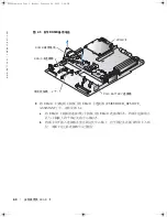
F i g u r e 1 - 4 .
I n s t a l l i n g t h e E R A / O C a r d
10
If you removed a ROMB backup battery in step 7, replace the battery. See Figure 1-3;
also see "Installing a ROMB Card" in your
Installation and Troubleshooting Guide
.
11
Replace the SCSI backplane. See Figure 1-2.
a
Fit the metal tabs at each end of the backplane into the slots in the chassis wall,
and lower the backplane into the chassis, ensuring that the CD and diskette drive
interface cables are not caught under the backplane.
b
Press down firmly over the handle to seat the backplane in its connector.
c
Pivot the release latch out into the securing slot in the chassis.
d
Connect the CD drive interface cable to the CD_ROM connector on the
backplane board.
e
Connect the diskette-drive interface cable to the FLOPPY connector on the
backplane board.
f
Press all installed hard drives firmly back into the SCSI connectors on the
backplane.
12
Close the system covers.
When closing the covers, close the right (larger) cover first and then close the left
cover. Press firmly on the left cover to snap the securing latch into place.
13
Install the optional security screw (if applicable). See Figure 1-1.
ERA/O card
retention clips (4)
ERA/O card connector
K0238ebk0.book Page 5 Monday, February 24, 2003 2:53 PM
Summary of Contents for PowerEdge 1750
Page 2: ...K0238fc0 fm Page 2 Monday February 24 2003 2 46 PM ...
Page 73: ...K0238am0 fm Page 1 Monday February 24 2003 2 48 PM ...
Page 75: ...K0238ap0 fm Page 1 Monday February 24 2003 2 48 PM ...
Page 77: ...K0238bp0 fm Page 1 Monday February 24 2003 2 49 PM ...
Page 79: ...K0238cc0 fm Page 1 Monday February 24 2003 2 49 PM ...
Page 81: ...K0238em0 fm Page 1 Monday February 24 2003 2 50 PM ...


