background image

support.dell.com

Rack Installation Guide

1-17

3.

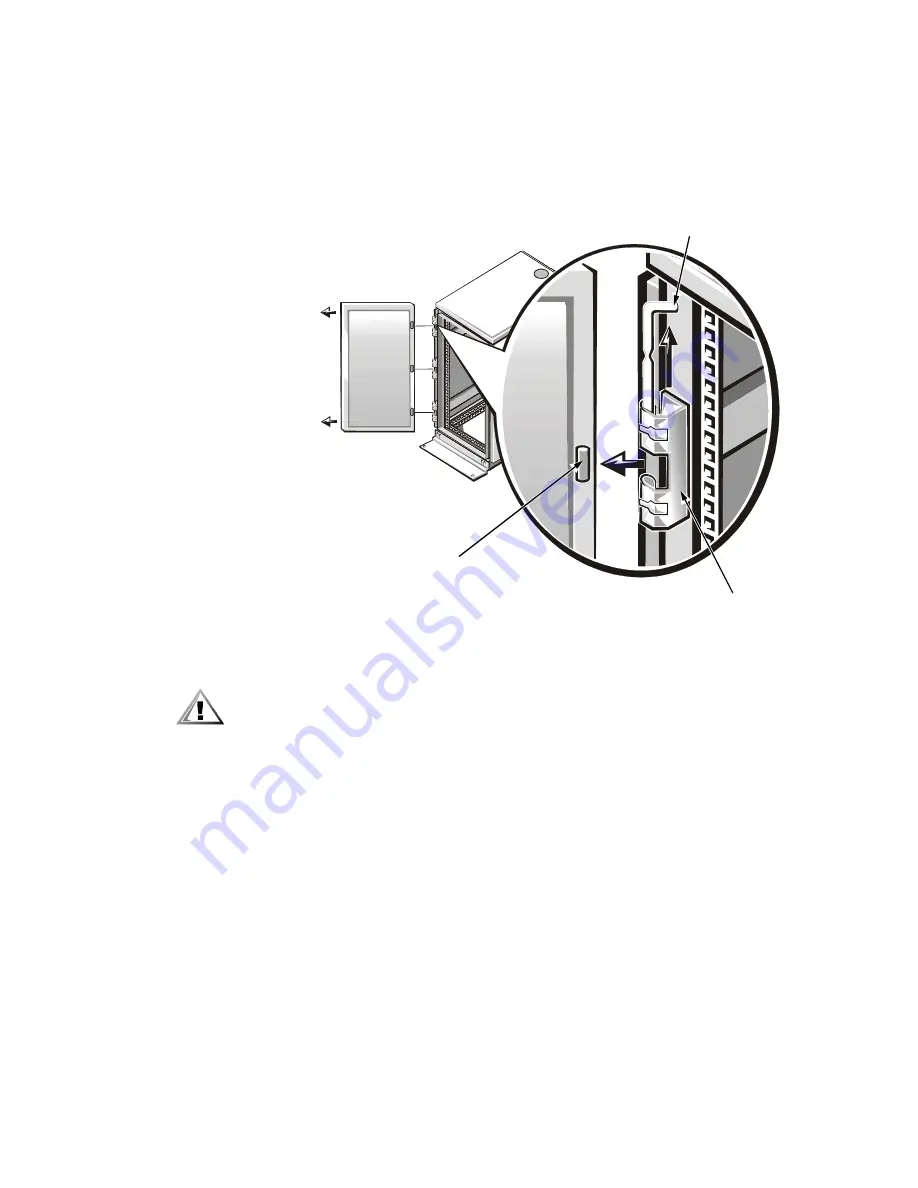
Remove the front door from the rack as shown in Figure 1-14.

a.

With the door open, lift out and fully retract all hinge pins.

b.

Once all the hinge pins have been lifted out and retracted, lift the door out. 

Figure 1-14.  Removing the 24-U Rack Doors

CAUTION: Store the two doors where they will not injure someone if the 
doors accidently fall over. 

If you want to reverse the door so that the handle is on the other side, perform the 
following steps:

1.

With the door open, lift out and fully retract all hinge pins.

2.

Remove the hinges and door brackets from the door frame.

3.

Replace the hinges and door brackets on the opposite side and switch the 
position of the handle.

4.

Replace the rack door (see the section, “Replacing the Rack Doors”, found later in 
this guide).

hinge insert

hinge

hinge pin

Summary of Contents for PowerApp 110

Page 1: ...www dell com support dell com Dell PowerApp 100 and 110 Appliances RACK INSTALLATION GUIDE ...

Page 2: ...ation is strictly forbidden Trademarks used in this text Dell the DELL E COM logo PowerEdge and PowerApp are trademarks of Dell Computer Corporation Other trademarks and trade names may be used in this document to refer to either the entities claiming the marks and names or their products Dell Computer Corporation disclaims any proprietary interest in trademarks and trade names other than its own ...

Page 3: ...E A NOTICE indicates either potential damage to hardware or loss of data and tells you how to avoid the problem CAUTION A CAUTION indicates a potentially hazardous situation which if not avoided may result in minor or moderate injury WARNING A WARNING indicates a potentially hazardous situation which if not avoided could result in death or serious bodily injury Precautions for Rack Mountable Produ...

Page 4: ...install the kit in any other rack be sure that the rack meets the specifications of a Dell rack Do not move large racks by yourself Due to the height and weight of the rack Dell recommends a minimum of two people to accomplish this task Before working on the rack make sure that the stabilizers are secure to the rack extend to the floor and that the full weight of the rack rests on the floor Instal...

Page 5: ...s 1 9 Installing the Appliance in the Rack 1 9 Installing Tab Covers 1 11 Four Post Rack Kit Installation 1 11 Rack Kit Contents 1 11 Before You Begin 1 13 Recommended Tools and Supplies 1 13 Installing the Rack Kit 1 13 Removing the Doors From the 42 U Rack 1 14 Removing the Doors From the 24 U Rack 1 16 Installing the Slide Assemblies in the Rack 1 18 Installing the Inner Rails on the Appliance ...

Page 6: ... 1 9 Figure 1 8 Securing the Appliance in the Rack 1 10 Figure 1 9 Installing the Tab Cover 1 11 Figure 1 10 Four Post Rack Kit Contents 1 12 Figure 1 11 Opening the 42 U Rack Door 1 14 Figure 1 12 Removing the 42 U Rack Doors 1 15 Figure 1 13 Opening the 24 U Rack Door 1 16 Figure 1 14 Removing the 24 U Rack Doors 1 17 Figure 1 15 One Rack Unit 1 18 Figure 1 16 Using Template to Mark Vertical Rai...

Page 7: ...s1 9 Figure 1 8 Securing the Appliance in the Rack1 10 Figure 1 9 Installing the Tab Cover1 11 Figure 1 10 Four Post Rack Kit Contents1 12 Figure 1 11 Opening the 42 U Rack Door1 14 Figure 1 12 Removing the 42 U Rack Doors1 15 Figure 1 13 Opening the 24 U Rack Door1 16 Figure 1 14 Removing the 24 U Rack Doors1 17 Figure 1 15 One Rack Unit1 18 Figure 1 16 Using Template to Mark Vertical Rails1 19 F...

Page 8: ...viii ...

Page 9: ...nd in telecommunications equipment facilities Both 3 inch and 6 inch wide two post racks are accommodated The two post open frame relay rack must be properly secured to the floor to the ceiling or upper wall and where applicable to adjacent racks using floor and wall fasteners and bracing specified or approved by the rack manufacturer or by industry standards Refer to the two post open frame relay...

Page 10: ...d Phillips screws Figure 1 1 Two Post Center Mount Rack Kit Contents Recommended Tools and Supplies You need the following tools and supplies to install the appliance in a two post open frame relay rack 2 Phillips screwdriver Masking tape or a felt tip pen for use in marking the mounting holes to be used center mount brackets 2 12 24 x 0 5 inch pan head Phillips screws 2 10 24 x 0 375 inch pan hea...

Page 11: ...liance in the lowest available position in the rack 2 Mark the upper and lower mounting positions on the two posts Each 1 U 1 75 inch vertical space has three holes with center to center spacing between holes beginning at the center of the top hole of a 1 U space of 0 625 0 625 and 0 5 inch see Figure 1 2 Figure 1 2 Two Post Open Frame Relay Rack 1 U Hole Spacing 1 75 inches 1 U 0 5 inch 0 625 inc...

Page 12: ...eight of the PowerApp appliance never attempt to install the appliance by yourself 1 Lift the appliance into position between the two posts with the hole in the mounting bracket aligned one hole above the mark you made in the two posts 2 Secure the appliance to the rack using a 12 24 x 0 5 inch screw through the mounting bracket to the front of the left and right posts see Figure 1 3 3 Attach the ...

Page 13: ...o post open frame relay rack manufacturer s installation documentation for precautionary warnings and information before attempting this installation CAUTION Do not attempt to install the PowerApp appliance into a two post open frame relay rack that has not been securely anchored in place Damage to the appliance and personal injury may result See Safety Instructions found earlier in this guide for...

Page 14: ... tools and supplies to install the appliance in a two post open frame relay rack 2 Phillips screwdriver Masking tape or a felt tip pen for use in marking the mounting holes to be used flush mount brackets 2 10 24 x 0 25 inch flat head Phillips screws 4 1 U template inner mounting rails 2 12 24 x 0 5 inch pan head Phillips screws 4 ...

Page 15: ...desired location 3 Position the bottom of the template in line with the desired bottom position of the computer chassis 4 Mark the upper and lower mounting positions on the vertical rails as shown by the V notches on the sides of the template Each 1 U 1 75 inch vertical space has three holes with center to center spacing between holes beginning at the center of the top hole of a 1 U space of 0 625...

Page 16: ... by yourself 1 Slide the back portion of the bracket to its widest opening and place the mount ing bracket into the rack with the bottom of the bracket at the marks you made earlier see Figure 1 6 2 Slide the back part of the bracket toward the front with the pins entering the lower screw holes in the rack at the marks you made earlier Secure the bracket front and back to the rack with a 12 24 x 0...

Page 17: ... chassis with the raised upper and lower rail surface facing outward see Figure 1 7 Figure 1 7 Securing the Inner Rails to the Appliance Chassis 2 Secure each inner rail to the chassis using two 10 32 x 0 25 inch flat head screws Installing the Appliance in the Rack CAUTION Due to the size and weight of the PowerApp appliance never attempt to install the appliance by yourself 1 Remove the optional...

Page 18: ...he captive fasteners at the outer edge of the front panel see Figure 1 8 An internally threaded stud projecting from the front of the tray flanges accepts the captive fastener on the front of the appliance Figure 1 8 Securing the Appliance in the Rack 4 Attach the front bezel if it was removed in step 1 to the appliance see the Troubleshooting Guide for instructions captive fasteners ...

Page 19: ...nstalling the Tab Cover 3 Hold the tab cover firmly onto the server tab and engage the thumbscrew with the receiving fastener on the slide bracket 4 Repeat steps 1 through 3 to install the tab cover on the other side of the appliance This completes the two post flush mount rack installation Four Post Rack Kit Installation This procedure provides instructions for installing a Dell PowerApp applianc...

Page 20: ...App appliance the slide assemblies may be preinstalled in the rack Figure 1 10 Four Post Rack Kit Contents cable management arm assembly slide assemblies with mounting brackets 1 pair 10 32 x 0 5 inch pan head Phillips screws 4 1 U template 10 24 x 0 375 inch pan head Phillips screws 6 ...

Page 21: ... storage system or appliance that is installed in a rack Recommended Tools and Supplies You need the following tools and supplies to install the appliance in a four post rack cabinet A 2 Phillips screwdriver A flat blade screwdriver Masking tape or a felt tip pen for use in marking the mounting holes to be used Installing the Rack Kit NOTES If you purchased a Dell rack along with your PowerApp app...

Page 22: ...is procedure provides instructions for removing doors from earlier 42 U Dell racks If you have a newer Dell PowerEdge 4210 rack refer to the procedures contained in the Dell PowerEdge 4210 Rack Installation Guide 1 Open the latch on the front door see Figure 1 11 Slide the button cover up as far as it will go press the push button rotate the handle clockwise until the latch releases and then pull ...

Page 23: ...of the door b The person holding the bottom of the door should press the hinge release lever on the bottom hinge and then pull the door away from the rack c The person holding the top of the door should press the hinge release lever on the top hinge and then pull the door away from the rack Figure 1 12 Removing the 42 U Rack Doors 3 Repeat steps 1 and 2 to remove the back door from the rack hinge ...

Page 24: ...24 U Rack CAUTION To prevent personal injury due to the size and weight of the doors never attempt to remove or replace the doors by yourself 1 Unlock and twist the handle clockwise see Figure 1 13 2 Open the front door Figure 1 13 Opening the 24 U Rack Door ...

Page 25: ... doors where they will not injure someone if the doors accidently fall over If you want to reverse the door so that the handle is on the other side perform the following steps 1 With the door open lift out and fully retract all hinge pins 2 Remove the hinges and door brackets from the door frame 3 Replace the hinges and door brackets on the opposite side and switch the position of the handle 4 Rep...

Page 26: ...l rails of the rack are marked by small indentations in 1 U increments see Figure 1 15 Figure 1 15 One Rack Unit For more information about requirements for installing components in a rack see the Dell Rack Advisor software available on the Dell World Wide Web site at http support dell com WARNING If you are installing more than one computer install the slide assemblies so that the first computer ...

Page 27: ...utwards as the template front Position the bottom of the template in line with the desired bottom position of the computer chassis 2 Mark the rack s front vertical rails with a felt tipped marker or place masking tape where the appliance s upper and lower edges will be located see Figure 1 16 Make a mark or place tape on the vertical rails next to the template s V shaped notches Figure 1 16 Using ...

Page 28: ... made in the vertical rails 4 Secure the front of the mounting bracket flange with a 10 32 x 0 5 inch pan head Phillips screw in the front vertical rail see Figure 1 17 5 Push back on the back mounting bracket flange until the mounting hook locks into the matching square hole on the back vertical rail 6 Repeat steps 3 through 5 for the remaining slide assembly on the other side of the rack Figure ...

Page 29: ...de of the chassis with three 10 24 x 0 375 inch pan head Phillips screws see Figure 1 18 Installing the Appliance in the Rack WARNING If you are installing more than one computer install the first computer in the lowest available position in the rack WARNING Never pull more than one component out of the rack at a time 1 Pull the two interior slide assemblies out of the rack until they lock in the ...

Page 30: ...ptive thumbscrews on each side of the front chassis panel to secure the appliance to the rack Installing the Cable Management Arm To install the cable management arm on the back of the computer perform the following steps 1 Facing the back of the rack cabinet locate the threaded hole on the back of the slide assembly and secure the end of the cable management arm the end having a bracket and capti...

Page 31: ...cards on the back of the PowerApp appliance 5 Connect the remaining cables to the computer For details see your appliance s Troubleshooting Guide and User s Guide 6 Secure the cables to the cable management arm a After connecting the cables to the computer unscrew the thumbscrews that secure the front of the server to the front vertical rail b Slide the appliance forward to the fully extended posi...

Page 32: ...ove or replace the doors by yourself 1 Lift the front door into position and align the hinges with the holes in the rack as shown in Figure 1 12 2 Slide the hinges into the holes in the rack until the hinge release levers lock the hinges into position 3 Close the door latch by rotating the handle counterclockwise until it stops push in the handle until it locks in position and then slide the butto...

Page 33: ...four post rack 1 22 cables routing 1 23 cautions iii contents illustrated four post kit 1 12 two post center mount kit 1 2 two post flush mount kit 1 6 contents listed four post kit 1 11 two post center mount kit 1 2 two post flush mount kit 1 5 D Dell Web site 1 18 doors removing 24 U 1 16 42 U 1 15 replacing 24 U rack 1 24 42 U rack 1 24 F four post Dell rack installation 1 11 H hole spacing two...

Page 34: ... rack 1 5 M marking the rack four post rack 1 19 two post center mount rack 1 3 two post flush mount rack 1 7 marking the vertical rails four post rack 1 19 N notational conventions iii notes iii P PowerEdge 4210 rack 1 14 1 24 R rack mount precautions 1 4 1 5 1 13 routing cables 1 23 T tab covers installing 1 11 template four post rack 1 12 two post flush mount 1 6 tools and supplies four post ki...

Reviews: