background image


14 


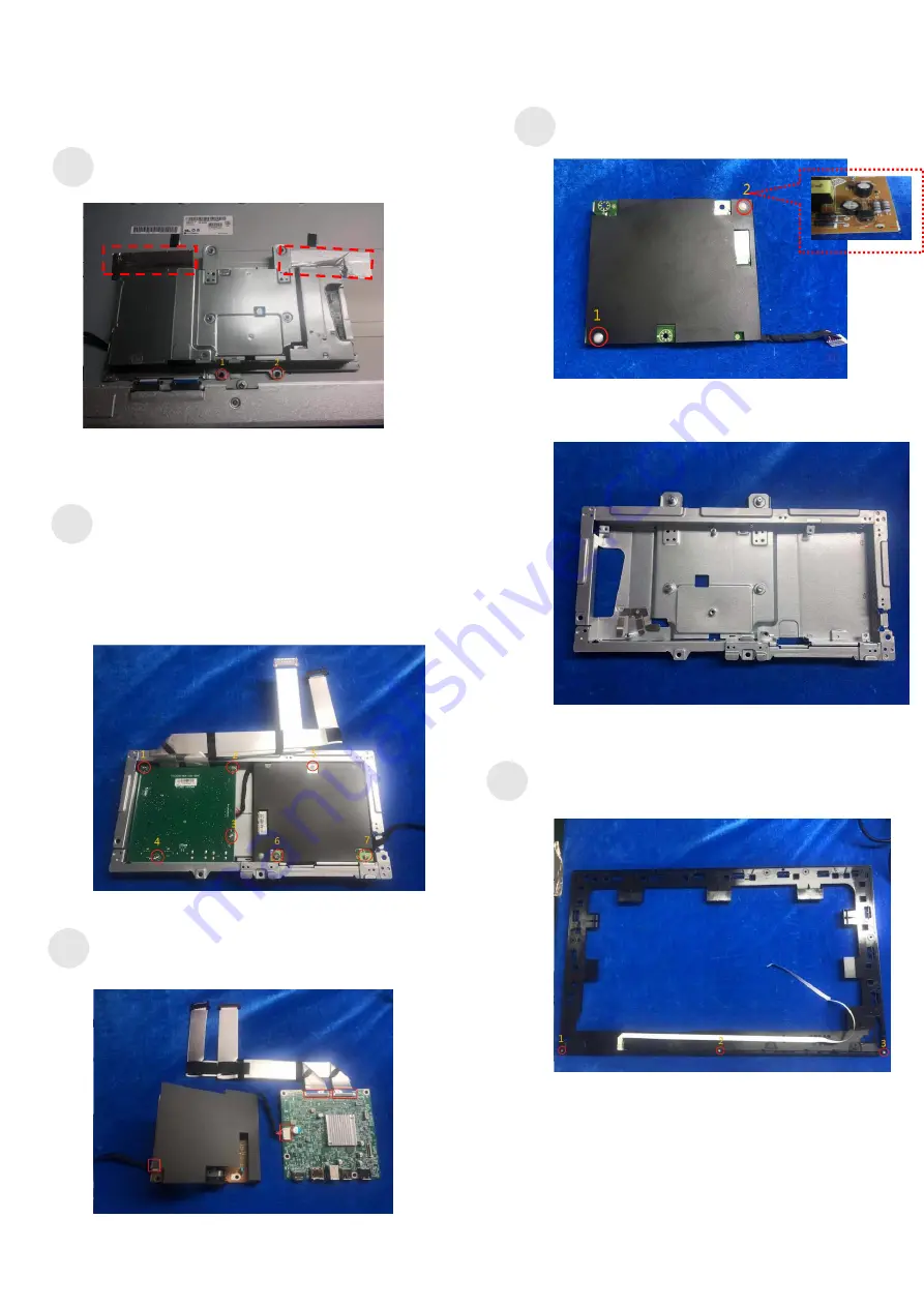
Tear off 2 pieces of aluminum foil. Use a 

Philips-head screwdriver to remove 2 screws 

for unlocking the mainframe


(No.1~2 Screw size=M3x4, Torque: 3±0.5kgf.cm)


Use a Philips-head screwdriver to remove 7 

screws for unlocking the main board and the 

adapter board 

(No.1~7 screw size=D3x6, Torque: 6±1kgf.cm) 

(No.9 screw size=M4x6, Torque: 6±1kgf.cm) 


Disconnect all of the cables to separate the 

power board and main board. 


Hold the plastic button on the power board to 

separate the Mylar from the power board. 


The Mainframe 


Use a Philips-head screwdriver to remove 3 screws 

for unlocking the bezel and the middle frame. 

(No.1~3 screw size=M2X2.5, Torque: 6±1kgf.cm)


S7


S8


S9


S10


S11


Summary of Contents for P2720D

Page 1: ...1 Service Manual P2720D Version 02 Date 2021 10 11 ...

Page 2: ...ETY General Power Safety 5 2 Exploded view diagram with list of items 6 3 Wiring connectivity diagram 8 4 How to connect and disconnect power cable connectivity cable 9 5 Disassembly and Assembly Procedures 11 5 1 Disassembly SOP 11 5 2 Assembly SOP 15 6 Trouble shooting instructions ...

Page 3: ...erenced in your computer documentation before placing a monitor or other devices on top of your computer Ensure that nothing rests on your equipment s cables and that the cables are not located where they can be stepped on or tripped over Ensure that all cables are connected to the appropriate connectors Some connectors have a similar appearance and may be easily confused for example do not plug a...

Page 4: ...nd then discharge into another object such as your computer To prevent ESD damage you should discharge static electricity from your body before you interact with any of your equipment s internal electronic components such as a memory module You can protect against ESD by touching a metal grounded object such as an unpainted metal surface on your computer s I O panel before you interact with anythi...

Page 5: ...as risk of electric shock and or fire Ensure that the ground prong of the power plug is inserted into the mating ground contact of the power strip Be sure to grasp the plug not the cable when disconnecting equipment from an electric socket If your equipment uses an AC adapter Use only the Dell provided AC adapter approved for use with this device Use of another AC adapter may cause a fire or explo...

Page 6: ...6 2 Exploded view diagram with list of items ...

Page 7: ...7 32 33 34 ...

Page 8: ...DLE FRAME 1 10 SCREW M3 4 11 11 SCREW M2 2 5 3 13 SCREW M3 6 2 14 SCREW M4 6 1 15 SCREW M3 6 4 16 POWER BOARD 1 17 SCALER BOARD 1 18 MYLAR 1 19 MAINFRAME 1 20 SCREW M3 6 2 21 SCREW M3 6 1 22 USB PCB 1 23 CREW M3 6 2 24 LATCH 1 25 LATCH SPRING 2 26 STAND BUTTON 1 27 SECURITY PLATE 28 REAR COVER 1 29 CREW M4 10 4 30 STAND 1 31 BASE 1 32 Power Cable 1 See NOTE 33 DP 1 2 cable 1 See NOTE ...

Page 9: ...t Dell 1 Go to https www dell com support 2 Verify your country or region in the Choose A Country Region drop down menu at the bottom right corner of the page 3 Click Contact Us next to the country dropdown 4 Select the appropriate service or support link based on your need 5 Choose the method of contacting Dell that is convenient for you ...

Page 10: ...10 3 Wiring connectivity diagram ...

Page 11: ...11 4 How to connect and disconnect power cable connectivity cable ...

Page 12: ...ll will deem warranty void if any disassembly is done on the monitors Tools Required List the type and size of the tools that would typically can be used to disassemble the product to a point where components and materials requiring selective treatment can be removed Tool Description Screwdriver Phillip head Hexagonal head Penknife ...

Page 13: ...ur fingers between the rear cover and the middle bezel on the corners of the top side of the monitor to release the rear cover then use Scraper to separate the rear cover in the below 3direction of the arrow Tear out all the cable to remove the rear cover and put it on a protective cushion Use a Philips head screwdriver to remove 11 screws for unlocking the middle plastic bezel with the whole unit...

Page 14: ...board and the adapter board No 1 7 screw size D3x6 Torque 6 1kgf cm No 9 screw size M4x6 Torque 6 1kgf cm Disconnect all of the cables to separate the power board and main board Hold the plastic button on the power board to separate the Mylar from the power board The Mainframe Use a Philips head screwdriver to remove 3 screws for unlocking the bezel and the middle frame No 1 3 screw size M2X2 5 To...

Page 15: ...unlocking the key board and the middle frame No 1 3 screw size M2X2 5 Torque 6 1kgf cm Use a Philips head screwdriver to remove 1 screws to remove the USB board Disconnect the cables of the USB board No 1 screw size M3x6 Torque 4 1kgf cm The USB Board S12 S13 ...

Page 16: ... Philips head screwdriver to lock 3 screws for assembling the key board and the middle frame No 1 3 screw size M2X2 5 Torque 6 1kgf cm Use a Philips head screwdriver to lock 3 screws for assembling the bezel and the middle frame No 1 3 screw size M2X2 5 Torque 6 1kgf cm Assemble the mylar on the powerboard and connect all of the cables between the power board and main board S2 S3 S4 ...

Page 17: ...the main board and the adapter board No 1 7 screw size D3x6 Torque 6 1kgf cm No 9 screw size M4x6 Torque 6 1kgf cm Stick 2 pieces of aluminum foil Use a Philips head screwdriver to lock 2 screws for locking the mainframe No 1 2 Screw size M3x4 Torque 3 0 5kgf cm S5 S6 ...

Page 18: ...e a Philips head screwdriver to lock 11 screws for locking the middle plastic bezel with the whole unit No 1 20 screw size M3x4 Torque 3 0 5kgfxcm Use a Philips head screwdriver to lock four screws for assembling the rear cover No 1 4 screw size M4x10 Torque 12 2kgf cm Assemble the stand S8 S9 ...

Page 19: ...19 6 Trouble shooting instructions ...

Page 20: ...20 ...

Page 21: ...21 ...

Page 22: ...22 ...

Page 23: ...23 ...

Reviews: