Dell P2222H Service Manual Download Page 14

  6. Trouble Shooting Instructions

Built-in diagnostics

Your monitor has a built-in diagnostic tool that helps you determine if any screen 
abnormality you experience is an inherent problem with your monitor, or with your 
computer and video card.

To run the built-in diagnostics:

1.  Ensure that the screen is clean (no dust particles on the surface of the 

screen). 

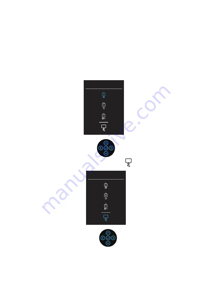
2.  Move and hold the joystick up/down/left/right about 4 seconds until a pop-

up menu appears. 

Select option:

3.  Move the joystick to highlight the Diagnostic icon 

then press the joystick 

to confirm. A gray test pattern appears.

Select option:

4.  Carefully inspect the screen for abnormalities.

5.  Press the joystick to change the test patterns.

6.  Repeat steps 4 and 5 to inspect the display in red, green, blue, black, white, 

and text screens.

7.  Press the joystick to end the diagnostic program.

Summary of Contents for P2222H

Page 1: ...Version 01 Date 2021 10 30 Service Manual P2222H ...

Page 2: ...ipment or products It is recommended that service engineers should have repairing knowledge experience as well as appropriate product training per new model before performing the service procedures NOTICE To avoid electrical shocks the products should be connected to an authorized power cord and turn off the master power switch each time before removing the AC power cord To prevent the product awa...

Page 3: ... service or support link based on your need 5 Choose the method of contacting Dell that is convenient for you Item Description Q ty Remark 1 1 For EMEA Only not for other regions 2 Panel Mylar 1 1 3 4 1 1 5 6 USB BD 1 1 7 8 1 9 10 11 1 1 Key BD 12 1 13 1 14 LED BD Front trim ASSY Middle Frame Interface BD Power BD 1 1 15 1 1 Main bracket 16 Joystick button See NOTE See NOTE Riser ASSY Base ASSY Ba...

Page 4: ...3 Wiring Connectivity Diagram ...

Page 5: ...4 How to connect and disconnect power cable connectivity cable WARNING To change power cable connectivity cable switch off power before unplugging the cable and replugging in required cable ...

Page 6: ...r cover Use a Philips head screwdriver to remove four screws for unlocking mechanisms No 1 4 screw size M4x10 Torque 12 0 5kgfxcm S3 S2 S1 2 3 4 1 1 3 2 2 S1 Remove the monitor stand base 1 Place the monitor on a soft cloth or cushion 2 Press and hold the stand release button 3 Lift the stand up and away from the monitor Lift the rear cover up carefully Disconnect the key cable and USB FFC cable f...

Page 7: ...ocking the bracket with panel No 1 screw size M3x0 5x3 Torque 4 0 5kgfxcm Use a Philips head screwdriver to remove 11pcs screws for unlocking the middle bezel with the panel No 1 9 screw size M3x4 Torque 5 0 5kgfxcm No 10 11 screw size M1 6x1 7 Torque 1 0 2kgfxcm S8 2 10 1 11 3 8 9 7 4 5 6 1 S9 S11 Take away the bracket chassis module and then put the bracket chassis module on a protective cushion...

Page 8: ...connect all the cables Use a Philips head screwdriver to remove 5pcs screws for unlocking the power board and interface board and then release all the cables from the hooks No 1 4 screw size M3x7 5 Torque 6 0 5kgfxcm No 5 screw size M4x8 Torque 6 0 5kgfxcm S14 S16 Use a Hex head screwdriver to remove two screws for unlocking the D Sub connector No 1 2 screws size M3x8 Torque 6 0 5kgfxcm S17 2 1 3 ...

Page 9: ...rface board connect a LVDS cable to the connector of the interface board then connect the cable of the power board to the connector of the interface board Turn over the interface board and locate it into the bracket Use a Philips head screwdriver to tighten 5pcs screws for locking the power board and interface board No 1 4 screw size M3x7 5 Torque 6 0 5kgfxcm No 5 screw size M4x8 Torque 6 0 5kgfxc...

Page 10: ...he LED board Fix the LED cable with 2pcs tapes on the middle bezel by tearing off papers and then connect the LED cable to the connector of the interface board 1 2 10 1 11 3 8 9 7 4 5 6 Assemble the middle bezel with the front bezel and panel module then adjust the middle bezel for two parts firmly attachment S10 Take a front bezel then lift up the panel with bracket and assemble the front bezel w...

Page 11: ...e foam on the back of the board Locate the USB board into the hook of the middle bezel Use a Philips head screwdriver to tighten one screw for locking the USB unit with middle bezel No 1 screw size M3x6 Torque 4 0 5kgfxcm S14 S17 2 3 4 1 Take 1pcs assembled stand base then fit the two tabs on the upper part of the stand into the grooves on the back of the monitor and then press the stand so that t...

Page 12: ...5 Disassembly and Assembly Procedures L video signal to the monitor ift up the monitor then provide power supply and a then turn on the monitor for functionality check S19 ...

Page 13: ...rrectly While in self test mode the power LED remains white Also depending upon the selected input one of the dialogs shown below will continuously scroll through the screen No VGA Cable The display will go into Standby mode in 4 minutes www dell com P2X22H or No HDMI Cable The display will go into Standby mode in 4 minutes www dell com P2X22H or No DP Cable The display will go into Standby mode i...

Page 14: ...particles on the surface of the screen 2 Move and hold the joystick up down left right about 4 seconds until a pop up menu appears Select option 3 Move the joystick to highlight the Diagnostic icon then press the joystick to confirm A gray test pattern appears Select option 4 Carefully inspect the screen for abnormalities 5 Press the joystick to change the test patterns 6 Repeat steps 4 and 5 to i...

Page 15: ...Source menu Poor Focus Eliminate video extension cables Reset the monitor to Factory Settings Factory Reset Change the video resolution to the correct aspect ratio Shaky Jittery Video Reset the monitor to Factory Settings Factory Reset Check environmental factors Relocate the monitor and test in another room Missing Pixels Cycle power On Off Pixel that is permanently Off is a natural defect that c...

Page 16: ... test feature check to determine if the intermittent problem occurs in self test mode Missing Color Perform monitor self test feature check Ensure that the video cable connecting the monitor to the computer is connected properly and is secure Check for bent or broken pins in the video cable connector Wrong Color Change the Color Setting Mode in the Color Settings OSD to Graphics or Video depending...

Page 17: ...full screen Run the built in diagnostics Universal Serial Bus USB specific problems Specific Symptoms Possible Solutions USB interface is not working Check that your monitor is turned On Reconnect the upstream cable to your computer Reconnect the USB peripherals downstream connector Turn off the monitor and turn it on again Reboot the computer Certain USB devices such as portable hard drive requir...

Reviews: