background image

Back to Contents Page


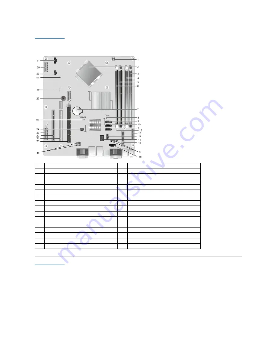
System Board Layout 

Dell™ OptiPlex™ XE Desktop Service Manual—

Desktop 


Back to Contents Page


1

processor power connector (12VPOWER)

2

processor socket (CPU)

3

memory module connectors (DIMM_4)

4

memory connector (DIMM_2)

5

memory module connectors (DIMM_3)

6

memory connector (DIMM_1)

7

battery socket (BATTERY)

8

password jumper (PSWD)

9

SATA drive connectors (SATA0)

10

SATA drive connectors (SATA1)

11

SATA drive connectors (SATA2)

12

thermal sensor connector (rear)

13

front-panel connector (FRONTPANEL)

14

external power USB connector

15

internal USB connector

16

power connector (POWER)

17

serial port jumper (J3 & J4)

18

power connector (24V POWER)

19

serial port jumper (J1 & J2)

20

PCI Express x16 slot (SLOT1) 

21

PCI slot (SLOT2) 

22

PCI slot ( SLOT3)

23

PCI Express x1 slot (SLOT4) 

24

chassis intrusion switch connector (INTRUDER)

25

RTC reset jumper (RTCRST)

26

Internal speaker (SPKR)

27

speaker (INT_SPKR)

28

thermal Sensor connector (front)

29

fan connector (FAN_HDD)

30

PCI Express slot x1 (Slot6)

31

fan connector (FAN_CPU)


Summary of Contents for OptiPlex XE

Page 1: ...Microsoft Windows Windows Server Windows Vista and the Windows Vista start button are either trademarks or registered trademarks of Microsoft Corporation in the United States and or other countries Adobe the Adobe logo and Adobe Flash Player are trademarks of Adobe Systems Incorporated Wi Fi is a registered trademark of Wireless Ethernet Compatibility Alliance Inc Other trademarks and trade names ...

Page 2: ...window System Setup Options Overview System Setup Options Booting to a USB Device Password Protection Clearing Forgotten Passwords Entering System Setup Boot Sequence Booting to a USB Device Jumper Settings Clearing CMOS Settings CAUTION Unless you are an expert computer user do not change the settings for this program Certain changes can make your computer work incorrectly NOTE The F12 prompt ind...

Page 3: ...he system board System Configuration Integrated NIC Integrated NIC 2 Enables or disables the integrated network card You can set the integrated NIC to l Enable default l Disable l Enable with PXE USB Controller Enables or disables the integrated USB controller You can set the USB controller to l Enable default l Disable l No boot Serial Port 1 Serial Port 2 Identifies and defines the serial port s...

Page 4: ...utrace service designed for asset management You can set this option to l Deactivate default l Disable l Activate SATA 0 Password SATA 1 Password Displays the current status of the password set for the hard drive connected to the SATA 0 connector on the system board You can also set a new password This option is not set by default NOTE The system setup program displays a password for each of the h...

Page 5: ... 2 0 Asset Tag Allows you to create a system asset tag if an asset tag is not already set This option is not set by default SERR Messages Controls the SERR Message mechanism This option is enabled by default Some graphics cards require the SERR Message mechanism be disabled Watchdog Timer Support Enables or disables Watchdog support Post Behavior Fast Boot When enabled default your computer starts...

Page 6: ...ice and adds the USB device option to the boot menu 3 From the boot menu select the number that appears next to the USB device The computer boots to the USB device Floppy Drive 1 In system setup set the Diskette Drive option to enable support for USB floppy drives 2 Save and exit system setup 3 Connect the USB floppy drive insert a bootable floppy and re boot the computer Password Protection Syste...

Page 7: ...the screen If Password Status is set to Locked Type the password and press Enter If you have assigned an administrator password the computer accepts your administrator password as an alternate system password If you type a wrong or incomplete system password the following message appears on the screen Incorrect password If you again type an incorrect or incomplete system password the same message ...

Page 8: ...rd a second time to confirm and press OK button The password setting changes to Set 5 Exit system setup A change to Admin Password becomes effective immediately no need to restart the computer Operating Your Computer With an Administrator Password Enabled When you enter system setup the Admin Password option is highlighted prompting you to type the password If you do not type the correct password ...

Page 9: ...ess the power button to ground the system board 9 Open the computer cover 10 Locate the 2 pin password jumper on the system board and attach the jumper to reenable the password feature 11 Replace the computer cover Jumper Setting Description PSWD Password features are enabled default setting Password features are disabled RTCRST The real time clock has not been reset The real time clock is being r...

Page 10: ...it back on the password pins 4 Replace the computer cover 5 Connect your computer and devices to electrical outlets and turn them on Back to Contents Page NOTE This procedure enables the password feature When you enter system setup see Entering System Setup both system and administrator password options appear as Not Set meaning that the password feature is enabled but no password is assigned WARN...

Page 11: ...Onboard or USB CD ROM Drive and press Enter 4 Select the Boot from CD ROM option from the menu that appears and press Enter 5 Type 1 to start the menu and press Enter to proceed 6 Select Run the 32 Bit Dell Diagnostics from the numbered list If multiple versions are listed select the version appropriate for your computer 7 When the Dell Diagnostics Main Menu appears select the test you want to run...

Page 12: ...evices from system setup memory and various internal tests and it displays the information in the device list in the left pane of the screen The device list may not display the names of all the components installed on your computer or all devices attached to your computer Parameters Allows you to customize the test by changing the test settings Power Light State Description Off Power is off light ...

Page 13: ...f the same type into your computer l If the problem persists contact Dell A possible graphics card failure has occurred l Reseat any installed graphics cards l If available install a working graphics card into your computer l If the problem persists contact Dell A possible floppy drive or hard drive failure has occurred Reseat all power and data cables A possible USB failure has occurred Reinstall...

Page 14: ...perating system is attempting to boot from a device such as the floppy drive or optical drive check system setup to ensure the boot sequence is correct for the devices installed on your computer l If the problem persists contact Dell ...

Page 15: ...esktop Back to Contents Page Cover Optical Drive Primary Hard Drive Heat Sink and Processor Memory Power Supply Back Plate Chassis Intrusion Switch Coin Cell Battery Front Panel Secondary Hard Drive Heat Sink Fan Fan Thermal Sensor Expansion Card I O Panel Internal Speaker System Board ...

Page 16: ... l Intel Celeron 440 512K Memory Type DDR3 SDRAM Speed 1066 MHz Connectors four DIMM slots Capacity 1 GB or 2 GB Minimum memory 1 GB Maximum memory 8 GB Video Video type Integrated integrated on system board Discrete PCI E x16 dual channel graphics card with one DVI port and one DisplayPort connector Video memory Integrated Microsoft Windows XP up to 512 MB shared video memory with 1 GB system mem...

Page 17: ...iser card two low profile cards with riser card two full height cards Small Form Factor one low profile card PCI Express x1 Desktop one low profile card Small Form Factor N A PCI Express x16 with support for PCI Express x1 Desktop without riser card one low profile card with riser card one full height card Small form factor one low profile card NOTE The PCI Express x16 slot is disabled when a disp...

Page 18: ...p one 164 pin x16 connector Small Form Factor one 164 pin x16 connector PCI Express x1 Data width one PCI Express lane Desktop one 36 pin connector Small Form Factor N A Serial ATA Desktop three 7 pin connectors Small Form Factor three 7 pin connectors Memory four 240 pin connectors Internal USB device one 10 pin connector supports two USB ports Processor fan one 5 pin connector Hard drive fan one...

Page 19: ...ight on integrated network adapter yellow light indicates that network activity is present Power DC power supply Wattage Desktop EPA 300 W Small Form Factor EPA 280 W Maximum heat dissipation Desktop EPA 1204 BTU hr Small Form Factor EPA 1124 BTU hr Voltage Desktop EPA 100 240 VAC 50 60 Hz 6 0 A Small Form Factor EPA 100 240 VAC 50 60 Hz 5 0 A NOTE Heat dissipation is calculated using the power su...

Page 20: ... six sides Maximum shock Operating HALF SN 40 G 2 ms two sides Storage HALF SN 105 G 2 ms six sides Altitude Operating below 3048 m 10 000 ft 42 C at 10 000 ft Storage below 10 668 m 35 000 ft Airborne contaminant level G2 or lower as defined by ISA S71 04 1985 ...

Page 21: ...TA1 11 SATA drive connectors SATA2 12 thermal sensor connector rear 13 front panel connector FRONTPANEL 14 external power USB connector 15 internal USB connector 16 power connector POWER 17 serial port jumper J3 J4 18 power connector 24V POWER 19 serial port jumper J1 J2 20 PCI Express x16 slot SLOT1 21 PCI slot SLOT2 22 PCI slot SLOT3 23 PCI Express x1 slot SLOT4 24 chassis intrusion switch conne...

Page 22: ...lacing the Back Plate To replace the back plate perform the above steps in reverse order Back to Contents Page WARNING Before working inside your computer read the safety information that shipped with your computer For additional safety best practices information see the Regulatory Compliance Homepage at www dell com regulatory_compliance NOTE You may need to install Adobe Flash Player from Adobe ...

Page 23: ... out of its connector on the system board Replacing the Expansion Card To replace the expansion card perform the above steps in reverse order Back to Contents Page WARNING Before working inside your computer read the safety information that shipped with your computer For additional safety best practices information see the Regulatory Compliance Homepage at www dell com regulatory_compliance NOTE Y...

Page 24: ...om the computer Replacing the Coin Cell Battery To replace the coin cell battery perform the above steps in reverse order Back to Contents Page WARNING Before working inside your computer read the safety information that shipped with your computer For additional safety best practices information see the Regulatory Compliance Homepage at www dell com regulatory_compliance NOTE You may need to insta...

Page 25: ...omputer Replacing the Cover To replace the cover perform the above steps in reverse order Back to Contents Page WARNING Before working inside your computer read the safety information that shipped with your computer For additional safety best practices information see the Regulatory Compliance Homepage at www dell com regulatory_compliance NOTE You may need to install Adobe Flash Player from Adobe...

Page 26: ...t sink fan to the heat sink assembly 5 Remove the heat sink fan from the computer Replacing the Heat Sink Fan To replace the heat sink fan perform the above steps in reverse order Back to Contents Page WARNING Before working inside your computer read the safety information that shipped with your computer For additional safety best practices information see the Regulatory Compliance Homepage at www...

Page 27: ...e from its routing guide on the chassis 9 Remove the screws that secure the fan to the chassis 10 Remove the fan from the computer Replacing the Fan To replace the fan perform the above steps in reverse order Back to Contents Page WARNING Before working inside your computer read the safety information that shipped with your computer For additional safety best practices information see the Regulato...

Page 28: ... the computer Replacing the Front Panel To replace the front panel perform the above steps in reverse order Back to Contents Page WARNING Before working inside your computer read the safety information that shipped with your computer For additional safety best practices information see the Regulatory Compliance Homepage at www dell com regulatory_compliance NOTE You may need to install Adobe Flash...

Page 29: ...r and data cables from the hard drive 7 Remove the hard drive assembly from the computer 8 Pull the blue latches to release the hard drive and lift the hard drive up and away from the hard drive assembly Replacing the Primary Hard Drive To replace the primary hard drive perform the above steps in reverse order Back to Contents Page WARNING Before working inside your computer read the safety inform...

Page 30: ...sconnect the power and data cables from the hard drive 6 Remove the hard drive from the computer Replacing the Secondary Hard Drive To replace the secondary hard drive perform the above steps in reverse order Back to Contents Page WARNING Before working inside your computer read the safety information that shipped with your computer For additional safety best practices information see the Regulato...

Page 31: ...e latch from under the cover latch and pull back the cover release latch to release the processor cover 7 Lift the processor cover 8 Remove the processor from its socket on the system board Replacing the Heat Sink and Processor To replace the heat sink and processor perform the above steps in reverse order Back to Contents Page WARNING Before working inside your computer read the safety informatio...

Page 32: ... and push down the switch to remove it from the computer Replacing the Chassis Intrusion Switch To replace the chassis intrusion switch perform the above steps in reverse order Back to Contents Page WARNING Before working inside your computer read the safety information that shipped with your computer For additional safety best practices information see the Regulatory Compliance Homepage at www de...

Page 33: ...ide the internal speaker upward to remove it from the computer Replacing the Internal Speaker To replace the internal speaker perform the above steps in reverse order Back to Contents Page WARNING Before working inside your computer read the safety information that shipped with your computer For additional safety best practices information see the Regulatory Compliance Homepage at www dell com reg...

Page 34: ... 7 Remove the screws that secure the I O panel to the chassis 8 Remove the I O panel from the computer Replacing the I O Panel To replace the I O panel perform the above steps in reverse order Back to Contents Page WARNING Before working inside your computer read the safety information that shipped with your computer For additional safety best practices information see the Regulatory Compliance Ho...

Page 35: ...its connector and remove it from the computer Replacing the Memory To replace the memory perform the above steps in reverse order Back to Contents Page WARNING Before working inside your computer read the safety information that shipped with your computer For additional safety best practices information see the Regulatory Compliance Homepage at www dell com regulatory_compliance NOTE You may need ...

Page 36: ...omputer 4 Lift the optical drive up and away from the computer Replacing the Optical Drive To replace the optical drive perform the above steps in reverse order Back to Contents Page WARNING Before working inside your computer read the safety information that shipped with your computer For additional safety best practices information see the Regulatory Compliance Homepage at www dell com regulator...

Page 37: ... supply release latch and slide the power supply toward the front of the computer 8 Remove the power supply from the computer Replacing the Power Supply To replace the power supply perform the above steps in reverse order Back to Contents Page WARNING Before working inside your computer read the safety information that shipped with your computer For additional safety best practices information see...

Page 38: ... internal speaker fan and thermal sensor cables from the system board 10 Remove the screws that secure the system board to the chassis 11 Lift the system board up and away from the chassis Replacing the System Board To replace the system board perform the above steps in reverse order Back to Contents Page WARNING Before working inside your computer read the safety information that shipped with you...

Page 39: ...ollow the procedures in Before Working Inside Your Computer 2 Disconnect the back thermal sensor cable from the system board 3 Press in on the release latch to release the back thermal sensor from the chassis WARNING Before working inside your computer read the safety information that shipped with your computer For additional safety best practices information see the Regulatory Compliance Homepage...

Page 40: ...4 Remove the back thermal sensor from the computer Replacing the Back Thermal Sensor To replace the back thermal sensor perform the above steps in reverse order Back to Contents Page ...

Page 41: ...ractices information see the Regulatory Compliance Homepage at www dell com regulatory_compliance CAUTION Many repairs may only be done by a certified service technician You should only perform troubleshooting and simple repairs as authorized in your product documentation or as directed by the online or telephone service and support team Damage due to servicing that is not authorized by Dell is no...

Page 42: ...ide Your Computer After you complete any replacement procedure ensure you connect any external devices cards and cables before turning on your computer 1 Replace the computer cover see Cover 2 Connect any telephone or network cables to your computer 3 Connect your computer and all attached devices to their electrical outlets 4 Turn on your computer 5 Verify that the computer works correctly by run...

Reviews: