background image

Dell™ OptiPlex™ FX160/160 Service Manual 


Notes, Notices, and Cautions 

If you purchased a Dell™ n Series computer, any references in this document to Microsoft® 

Windows

® 

operating systems are not applicable. 

Information in this document is subject to change without notice. 

© 2008 Dell Inc. All rights reserved.


Reproduction of this material in any manner whatsoever without the written permission of Dell Inc. is strictly forbidden. 

Trademarks used in this text: 

Dell

, the 

DELL

 logo, and 

OptiPlex

 are trademarks of Dell Inc.; 

Intel

 is registered trademarks of Intel Corporation in the U.S. and other countries; 

Microsoft

Windows

Windows Vista

, the 

Windows Start button

, and

 Outlook 

are registered trademarks of Microsoft Corporation in the United States and/or other countries. 

Other trademarks and trade names may be used in this document to refer to either the entities claiming the marks and names or their products. Dell Inc. disclaims any 
proprietary interest in trademarks and trade names other than its own. 

Model DC01T


September 2008      Rev. A00


Working on Your Computer 


System Setup 


Selective USB 


Reinstalling Software 


Troubleshooting 


Computer Stand 


Covers 


Hard Drive Assembly (Optional) 


NVRAM Module 


Wireless Card 


I/O Board 


Power Supply 


Processor Heatsink Assembly 


Memory 


Coin-Cell Battery 


Cable Guide 


Antenna 


System Board Assembly 


Getting Help 


Finding Information 


NOTE: 

A NOTE indicates important information that helps you make better use of your computer. 


CAUTION: 

A CAUTION indicates potential damage to hardware or loss of data if instructions are not followed. 


WARNING: 

A WARNING indicates a potential for property damage, personal injury, or death. 

Summary of Contents for OptiPlex 160

Page 1: ... the United States and or other countries Other trademarks and trade names may be used in this document to refer to either the entities claiming the marks and names or their products Dell Inc disclaims any proprietary interest in trademarks and trade names other than its own Model DC01T September 2008 Rev A00 Working on Your Computer System Setup Selective USB Reinstalling Software Troubleshooting...

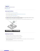
Page 2: ...talled from the opening for the antenna in the back panel 2 If missing install an antenna holder in the opening for the antenna in the back panel 3 Route the antenna wires through the antenna holder on the back of the chassis 4 Align the antenna bushing with the antenna holder of the back panel so that when you flip up the antenna it will be above the computer when the computer is in vertical orie...

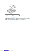
Page 3: ...k of the chassis so that the wire mesh surrounding the cable is under the tab 8 Replace the hard drive bracket assembly if it was removed see Replacing the Hard Drive Bracket Assembly 9 Perform the procedure in After Working on Your Computer Back to Contents Page 1 antenna holder 2 bushing tabs 3 wire mesh ...

Page 4: ...t WARNING Before working inside your computer read the safety information that shipped with your computer For additional safety best practices information see the Regulatory Compliance Homepage at www dell com regulatory_compliance WARNING Some components become very hot during normal operation Allow system components to cool before touching them CAUTION Only a certified service technician should ...

Page 5: ...over see Replacing the Computer Cover 2 Replace the computer stand see Replacing the Computer Stand 3 Connect a network cable to your computer if necessary 4 Connect your computer and all attached devices to their electrical outlets 5 Turn on your computer Back to Contents Page WARNING To guard against electrical shock always unplug your computer from the electrical outlet before removing the comp...

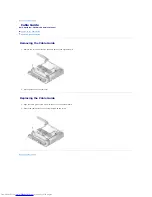
Page 6: ...ble Guide Removing the Cable Guide 1 Remove the screw that secures the cable guide to the system board 2 Lift the guide out of the computer Replacing the Cable Guide 1 Align the cable guide screw hole with the hole on the system board 2 Secure the cable guide to the system board with the screw Back to Contents Page ...

Page 7: ...he battery out of the socket Replacing the Coin Cell Battery 1 Slide the battery into the battery socket a slight angle to bypass the retaining clip s 2 Position the battery upright such that it is seated properly and securely held in place by the retainers 3 Perform the procedure in After Working on Your Computer 4 Restart your computer and enter the BIOS setup to configure option settings as nee...

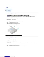
Page 8: ...nd lift it off Replacing the Computer Cover 1 Place the computer in a horizontal position 2 Place the computer cover on top of the computer The tab with the security cable slot should be toward the back of the computer and the cover should be approximately 1 4 inch from the system lock tabs being aligned 3 Slide the cover toward the back of the computer until the system lock tabs are aligned 4 Rep...

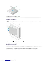
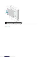
Page 9: ...the slots on the side of the chassis Replacing the Side Cover 1 With the side cover at a 30 degree angle to the chassis slip the hooks under the front edge of the side cover into the slots for the side cover on the left side of the chassis 2 Swing the back edge of the side cover into the chassis to engage the pegs under the back edge of the cover with the chassis retainers 1 side cover 2 side cove...

Page 10: ...Back to Contents Page 1 peg 2 2 peg retainer 2 3 side cover hooks 2 4 side cover hook slots 2 ...

Page 11: ... com l Readme files NOTE Readme files may be included on your media to provide last minute updates about technical changes to your computer or advanced technical reference material for technicians or experienced users Operating System Media The Operating System media is a CD or DVD that may have shipped with your computer l Reinstall your operating system Safety Regulatory Warranty and Support Doc...

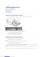
Page 12: ...hard drive cables to the system board see System Board Connectors a Connect the hard drive SATA data cable to the system board b Connect the SATA hard drive power cable to the system board c Connect the hard drive fan cable to the system board 2 Set the bracket assembly in place on the system board aligning the two captive screws in the bracket feet with the screw holes in the system board and the...

Page 13: ...r missing 2 Place the hard drive in the carrier with the label facing up and the cable connectors toward the open end of the bracket 3 Secure the hard drive to the bracket assembly affixing the four screws through the rubber grommets 4 Connect the SATA data power cable to the hard drive 1 SATA hard drive power cable 2 fan cable 3 cable retaining clip 4 SATA data cable 5 bracket screw 6 captive scr...

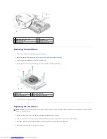
Page 14: ...acing the Hard Drive Fan 1 Position the fan in the hard drive bracket see Removing the Hard Drive Fan The screw hole on one corner of the fan should be under the tab on the bottom of the hard drive bracket assembly The other screw hole should be placed on the post of the hard drive bracket assembly 2 Secure the fan to the hard drive bracket with two screws one inserted from below the hard drive br...

Page 15: ...ssembly 1 If installing the heatsink assembly onto a different system board clean the thermal interface material or thermal grease from the surface of the heatsink and apply new thermal grease as needed 2 Align the two captive screws on the processor heatsink assembly with the screw holes on the system board 3 Tighten the two captive screws to secure the processor heatsink assembly to the system b...

Page 16: ...4 Replace the hard drive bracket assembly if it was removed see Replacing the Hard Drive Bracket Assembly 5 Perform the procedure in After Working on Your Computer Back to Contents Page ...

Page 17: ...and Customer Service Dell s support service is available to answer your questions about Dell hardware Our support staff uses computer based diagnostics to provide fast accurate answers To contact Dell s support service see Before You Call and then see the contact information for your region or go to support dell com DellConnect DellConnect is a simple online access tool that allows a Dell service ...

Page 18: ...port on your order For the telephone number to call for your region see Contacting Dell Problems With Your Order If you have a problem with your order such as missing parts wrong parts or incorrect billing contact Dell for customer assistance Have your invoice or packing slip available when you call For the telephone number to call for your region see Contacting Dell Product Information If you nee...

Page 19: ...page and select the appropriate service or support link based on your need 3 Choose the method of contacting Dell that is convenient for you Back to Contents Page NOTE Have your Express Service Code ready when you call The code helps Dell s automated support telephone system direct your call more efficiently You may also be asked for your Service Tag located on the back or bottom of your computer ...

Page 20: ...re clear of the cable guide 4 Disconnect the three cables Audio USB and Front Panel from the I O board Replacing the I O Board 1 Connect the three I O board cables Audio USB and Front Panel to the I O board 2 Place the cables under the cable guide metal tab and align the holes in the I O board with the screw holes on the chassis ensuring that the middle of the I O board rests in the metal clip 3 S...

Page 21: ...4 Perform the procedure in After Working on Your Computer Back to Contents Page 1 cable guide metal tab 2 metal clip ...

Page 22: ...uring clips lock into place If the clips do not click into place remove the module and reinstall it NOTE Your computer supports non ECC 667 MHz or 800 MHz DDR2 SDRAM only It supports memory module sizes of 512 MB for embedded Linux operating systems only 1 GB and 2 GB When 800 MHz memory is installed your computer operates at 667 MHz See support dell com for more information 1 DIMM_1 memory connec...

Page 23: ...3 Perform the procedure in After Working on Your Computer Back to Contents Page connector 3 DIMM_2 memory connector 4 securing clip two per connector white DIMM_1 black DIMM_2 ...

Page 24: ...crew that secures the NVRAM module to the system board with a Phillips 1 screwdriver 4 Lift the NVRAM module straight up from the system board Replacing the NVRAM Module 1 Align the NVRAM module connectors with the connectors on the system board and push down see System Board Connectors 2 Secure the NVRAM module to the system board with the screw 3 Replace the hard drive bracket assembly if it was...

Page 25: ...Back to Contents Page ...

Page 26: ...ctors 3 Remove the back panel screw 4 Remove the chassis screw 5 Slide the power supply slightly toward the front of the computer and lift up out of the chassis Replacing the Power Supply 1 Place the power supply in the chassis and slide it back against the back panel WARNING The power supply can become very hot during normal operation Allow the power supply to cool before touching it 1 power supp...

Page 27: ...supply with a back panel screw and the chassis screw 3 Connect the 12V power supply connector to the system board see System Board Connectors 4 Perform the procedure in After Working on Your Computer Back to Contents Page ...

Page 28: ...ce Manager 2 Scroll down the list to see if any device has an exclamation point a yellow circle with a on the device icon If an exclamation point is next to the device name you may need to reinstall the driver or install a new driver see Reinstalling Drivers and Utilities Reinstalling Drivers and Utilities Returning to a Previous Device Driver Version Microsoft Windows XP and Windows XP Embedded 1...

Page 29: ...omputer a Click Start Control Panel b If the Control Panel window appears in Category View Pick a category switch to Classic View icon view c Double click the System icon d In the System Properties window click the Hardware tab and then click Device Manager 2 Right click the device for which you need a driver and click Update Driver 3 Follow the instructions on the Hardware Update Wizard screens t...

Page 30: ...upport dell com Restoring Microsoft Windows Operating Systems on Hard Drives Starting System Restore Windows XP 1 Click Start All Programs Accessories System Tools System Restore 2 Click either Restore my computer to an earlier time or Create a restore point 3 Click Next and follow the remaining on screen prompts Windows Vista 1 Click the Windows Vista Start button 2 In the Start Search box type S...

Page 31: ...in Windows Windows XP Embedded 1 Click Start Control Panel 2 If the Control Panel window appears in Category View Pick a category switch to Classic View icon view CAUTION Before performing the installation back up all data files on your primary hard drive For conventional hard drive configurations the primary hard drive is the first drive detected by the computer NOTE The Dell Drivers and Utilitie...

Page 32: ...f the Control Panel window appears in Category View Pick a category switch to Classic View icon view 3 Click User Accounts 4 Click the User Name whose password or privileges you want to change and follow the on screen instructions Windows Vista 1 Click the Windows Vista Start button 2 Click Control Panel User Accounts 3 Click the item on the screen that you want to change Back to Contents Page ...

Page 33: ...1 4 of an inch 3 Remove the stand from the computer Replacing the Computer Stand 1 Grasp the computer by the top of the chassis 2 With the part of the stand that has the clip at the back of the computer align the tabs on the stand with the slots in the bottom of the chassis and insert the tabs into the chassis The stand should overlap the back of the computer by approximately 1 4 of an inch 3 Slid...

Page 34: ...Removing the Processor Heatsink Assembly 7 Remove the I O board see Removing the I O Board 1 memory connector DIMM_1 2 memory connector DIMM_2 3 battery BATTERY 4 audio connector AUDIOF1 5 USB connector USBF1 6 setup jumper SETUP_LOCK 7 front panel connector FRONTPANEL 8 SATA data cable connector SATA_1 9 NVRAM module connector SATA_0 10 clear CMOS jumper RTCRST 11 clear password jumper PSWD 12 WL...

Page 35: ...acing the Cable Guide 3 Replace the two screws on the back corners of the system board that secure it to the chassis see System Board Connectors 4 Connect the 12V power supply connector to the system board 5 Replace the I O board see Replacing the I O Board 6 Connect the I O board cables to the system board 7 Replace the cable guide see Replacing the Cable Guide 8 Replace the memory module s see R...

Page 36: ...ocessor Heatsink Assembly 12 Replace the hard drive bracket assembly if it was removed see Replacing the Hard Drive Bracket Assembly 13 Perform the procedure in After Working on Your Computer 14 Restart your computer and enter the BIOS setup to configure parameter settings as needed see Entering the BIOS Setup Utility Back to Contents Page ...

Page 37: ...ter work incorrectly NOTE The Dell logo appears very quickly so you must watch for it to display If you press F2 before you are prompted the computer cannot acknowledge the keystroke BIOS screen change screens with left and right arrow keys Options List This field appears on the left side of the BIOS Setup Utility screen The field is a scrollable list containing parameters that define the configur...

Page 38: ...enable status of the hyperthreading feature CPUID value and HDD acoustic mode Security Displays the enable status of passwords controlling access to BIOS setup and hard disk drive Power Management AC Recovery Specifies how the system reacts after a power loss Off On Last previous state Auto Power On Specifies when to use the Auto Power Time setting Off Everyday Weekdays Auto Power Time Specifies a...

Page 39: ...sequence order of device types the computer will attempt to boot from 6 Press F10 and then press Enter to save your settings and reboot your system Select Specific Boot Device During system startup you can select any bootable device such as an internal or external hard drive an external CD or DVD drive USB memory key or external floppy drive without changing the boot device sequence in the BIOS Th...

Page 40: ...BIOS update file for your computer at support dell com 3 Click Download Now to download the file 4 If the Export Compliance Disclaimer window appears click Yes I Accept this Agreement The File Download window appears 5 Click Save this program to disk and then click OK The Save In window appears 6 Click the down arrow to view the Save In menu select Desktop and then click Save The file downloads to...

Page 41: ...Back to Contents Page ...

Page 42: ...n the U S and other countries Microsoft Windows Windows Vista the Windows Start button and Outlook are registered trademarks of Microsoft Corporation in the United States and or other countries Other trademarks and trade names may be used in this document to refer to either the entities claiming the marks and names or their products Dell Inc disclaims any proprietary interest in trademarks and tra...

Page 43: ...he NVRAM module if installed see NVRAM Module Remove and then reinstall the wireless card if installed see Wireless Card l Eliminate interference Some possible causes of interference are Power keyboard and mouse extension cables Too many devices on a power strip Multiple power strips connected to the same electrical outlet Diagnostic Lights To help troubleshoot a problem your computer has four dia...

Page 44: ...sible USB failure has occurred l Reinstall all USB devices check cable connections and then restart the computer l If the problem persists contact Dell see Contacting Dell No memory modules are detected l If two memory modules are installed remove the modules see Removing a Memory Module then reinstall one module see Replacing a Memory Module and restart the computer If the computer starts normall...

Page 45: ...the drive l If the hard drive is your boot device ensure that the cables are connected and that the drive is installed properly and partitioned as a boot device see Hard Drive Assembly Optional l Enter the BIOS Setup Utility and ensure that the boot sequence information is correct see Entering the BIOS Setup Utility No timer tick interrupt A chip on the system board might be malfunctioning or moth...

Page 46: ...steps Microsoft Windows XP 1 Click Start Help and Support 2 Type hardware troubleshooter in the search field and press Enter to start the search 3 In the Fix a Problem section click Hardware Troubleshooter 4 In the Hardware Troubleshooter list select the option that best describes the problem and click Next to follow the remaining troubleshooting steps Microsoft Windows Vista 1 Click the Windows V...

Page 47: ...vice you want to test is displayed in the BIOS Setup Utility and is active 1 Connect an external optical drive to the computer 2 Insert the Drivers and Utilities media into the optical drive 3 Restart your computer 4 When the DELL logo appears press F12 immediately 5 When the boot device list appears use the up or down arrow keys to highlight CD DVD CD RW Drive then press Enter NOTE If your comput...

Page 48: ... Test System to run a complete test on your computer Selecting Test Memory initiates the extended memory test which can take up to thirty minutes or more to complete When the test completes record the test results and then press any key to return to the previous menu NOTE Write down any error codes and problem descriptions exactly as they appear and follow the instructions on the screen Option Fun...

Page 49: ...properly Tab Function Results Displays the results of the test and any error conditions encountered Errors Displays error conditions encountered error codes and the problem description Help Describes the test and any requirements for running the test Configuration Displays the hardware configuration for the selected device The Dell Diagnostics obtains configuration information for all devices from...

Page 50: ... Turn off standby mode in Windows before writing to a disc Search for the keyword standby in Windows Help and Support for information on power management modes Hard drive problems Run Check Disk Windows XP Extended 1 Log in to the system as a user with administrative privileges 2 Right click the Start button and click Explore 3 In the Folders list right click the disk you want to check OS C or OS ...

Page 51: ...n any of the following characters Do not use these characters in filenames A required DLL file was not found The program that you are trying to open is missing an essential file To remove and then reinstall the program Windows XP and XP Embedded 1 Attempt to remove the program with the program s uninstall utility if provided If that is unsuccessful continue with the following steps 2 Log in to the...

Page 52: ... connect the keyboard directly to the computer Test the keyboard Connect a properly working keyboard to the computer then try using the keyboard Run the Hardware Troubleshooter See Hardware Troubleshooter Lockups and Software Problems The computer does not start up Check the diagnostic lights See Diagnostic Lights Ensure that the power cable is firmly connected to the computer and to the electrica...

Page 53: ... program so that it runs in an environment similar to non XP operating system environments 1 Click Start All Programs Accessories Program Compatibility Wizard Next 2 Follow the instructions on the screen Windows Vista The Program Compatibility Wizard configures a program so that it runs in an environment similar to non Windows Vista operating system environments 1 Click Start Control Panel Program...

Page 54: ... memory l Ensure that you are following the memory installation guidelines see Memory l Ensure that the memory you are using is supported by your computer For more information about the type of memory supported by your computer see Memory l Run the Dell Diagnostics see Dell Diagnostics Mouse Problems Check the mouse cable l Ensure that the cable is not damaged or frayed and check cable connectors ...

Page 55: ... Yellow indicates a 1000 Mbps connection If either the Activity LED or Link LED is off no network communication is occurring Replace the network cable Restart the computer and log on to the network again Check your network settings Contact your network administrator or the person who set up your network to verify that your network settings are correct and that the network is functioning Run the Ha...

Page 56: ...mentation for setup and troubleshooting information Ensure that the printer is turned on Check the printer cable connections l See the printer documentation for cable connection information l Ensure that the printer cables are securely connected to the printer and the computer Test the electrical outlet Ensure that the electrical outlet is working by testing it with another device such as a lamp V...

Page 57: ... listed Windows recognizes the scanner Windows Vista 1 Click Start Control Panel Hardware and Sound Scanners and Cameras 2 If the scanner is listed Windows recognizes the scanner Reinstall the scanner driver See the scanner documentation for instructions Sound and Speaker Problems No sound from speakers Check the speaker cable connections Ensure that the speakers are connected as shown on the setu...

Page 58: ...uble click the speaker icon in the lower right corner of your screen Ensure that the volume is turned up and that the sound is not muted Mouse Problems Check the mouse settings 1 Click Start Control Panel Printers and Other Hardware Mouse 2 Try adjusting the settings Check the mouse cable Shut down the computer Disconnect the mouse cable check it for damage and firmly reconnect the cable If you ar...

Page 59: ...contrast and brightness demagnetizing degaussing the monitor and running the monitor self test Move the monitor away from external power sources Fans fluorescent lights halogen lamps and other electrical devices can cause the screen image to appear shaky Turn off nearby devices to check for interference Rotate the monitor to eliminate sunlight glare and possible interference Adjust the Windows dis...

Page 60: ......

Page 61: ...mputer and press F2 to enter the BIOS Setup Utility see Entering the BIOS Setup Utility 4 Use the Onboard Devices screen to enable Selective USB When enabled the two selective USB ports will function with authorized USB devices only All other USB ports will be disabled 5 Save the settings and reboot the computer During POST the BIOS will check whether authorized USB devices are connected to the se...

Page 62: ...pops up at a 45 degree angle 4 Pull the wireless card out of the system board connector 5 Disconnect the antenna cables from the wireless card Replacing the Wireless Card 1 Connect the white antenna cable to the connector marked with the white triangle and connect the black antenna cable to the connector labeled with a black triangle 2 Insert the wireless card into the WLAN connector on the system...

Page 63: ... mesh sleeve on the cable is secured by the tab on the back panel 5 Replace the hard drive bracket assembly if it was removed see Replacing the Hard Drive Bracket Assembly 6 Perform the procedure in After Working on Your Computer Back to Contents Page ...

Reviews: