Installing the Media Board
1. Align the media board to its original position on the computer.
2. Replace and tighten the screws that secure the media board to the
computer.
3. Connect the media board cable to the system board.
4. Install the ATG Handle (for E6420 ATG systems only).
5. Install the ATG Port Cover (for E6420 ATG systems only).
6. Install the
Palmrest Assembly
.
7. Install the
Keyboard
.
8. Install the
Keyboard Trim
.
9. Install the
WWAN Card
.
10. Install the
Bluetooth Card
.
11. Install the
Hard Drive
.
12. Install the
Optical Drive
.
13. Install the
Base Cover
.
14. Install the
SD Card
.
15. Install the
Battery
.
16. Install the
ATG Port Cover
(only for E6420 ATG systems).
17. Install the
ATG Handle
(only for E6420 ATG systems).
18. Follow the procedures in
After Working Inside Your Computer
.
75
Summary of Contents for Latitude E6420
Page 8: ...8 ...
Page 20: ...20 ...
Page 26: ...26 ...
Page 38: ...9 Slide and remove the WLAN card out from its slot on the system board 38 ...
Page 40: ...40 ...
Page 42: ...9 Slide the WWAN card from its connector and remove it from the computer 42 ...
Page 44: ...44 ...
Page 50: ...50 ...
Page 52: ...10 Disconnect the bluetooth cable 52 ...
Page 54: ...54 ...
Page 59: ...9 Remove the tape securing the keyboard cable from the keyboard 10 Unlock the cable holder 59 ...
Page 64: ...64 ...
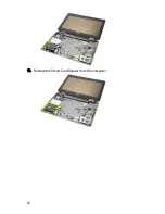
Page 70: ...13 Remove the Smart Card Reader from the computer 70 ...
Page 72: ...72 ...
Page 74: ...16 Remove the media board from the computer 74 ...
Page 76: ...76 ...
Page 80: ...22 Remove the screws from the video cable holder 23 Remove the video cable holder 80 ...
Page 83: ...29 Slide to unlock system board from the port connectors 30 Remove the system board 83 ...
Page 86: ...23 Unthread the speaker cable 24 Remove the speaker from the system 86 ...
Page 88: ...88 ...
Page 90: ...24 Unthread the video and wireless antenna cables 25 Unthread the modem cable 90 ...
Page 92: ...29 Remove the whole modem cable assembly by pulling it out from the base 92 ...
Page 94: ...94 ...
Page 96: ...22 Remove the I O board from the computer 96 ...
Page 98: ...98 ...
Page 100: ...23 Remove the DC in bracket 24 Remove the DC in cable from the system 100 ...
Page 101: ...25 Push in the DC in trim and remove it from the system 101 ...
Page 105: ...105 ...
Page 109: ...109 ...
Page 116: ...116 ...
Page 118: ...118 ...
Page 128: ...128 ...
Page 144: ...144 ...


