6. Remove the
.
7. Remove the
.
8. Remove the
.
9. Remove the
.
10. Remove the
11. Remove the
.
12. Remove the
.
13. Remove the
14. Remove the
.
15. Remove the
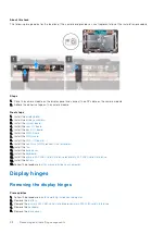
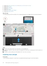
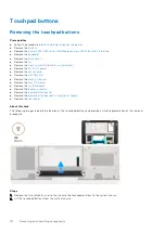
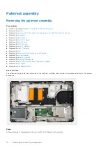
About this task
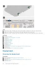
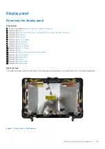
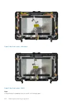
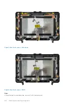
The following images indicate the location of the display hinges and provide a visual representation of the removal procedure.
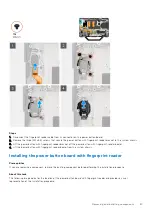
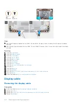
Steps
1. Remove the two (M3x7, T8) and (M3x5, T8) epoxy screws that secure the left hinge to the display assembly.
2. Remove the two (M3x7, T8) and (M3x5, T8) epoxy screws that secure the right hinge to the display assembly.
3. Lift to remove the left and right hinges from the display assembly.
Installing the display hinges
Prerequisites
If you are replacing a component, remove the existing component before performing the installation procedure.
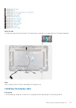
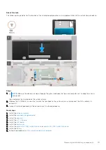
About this task
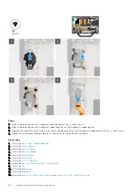
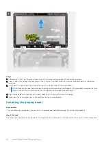
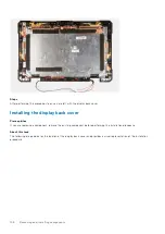
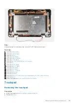
The following image indicates the location of the display hinges and provides a visual representation of the installation
procedure.
Removing and installing components
99
Summary of Contents for Latitude 5430
Page 19: ...Removing and installing components 19 ...
Page 21: ...Removing and installing components 21 ...
Page 25: ...Removing and installing components 25 ...
Page 31: ...Removing and installing components 31 ...
Page 34: ...34 Removing and installing components ...
Page 69: ...Removing and installing components 69 ...
Page 73: ...Removing and installing components 73 ...
Page 90: ...90 Removing and installing components ...
Page 95: ...Removing and installing components 95 ...
Page 138: ...138 Troubleshooting ...


