background image

Installing hard disk drive (HDD)

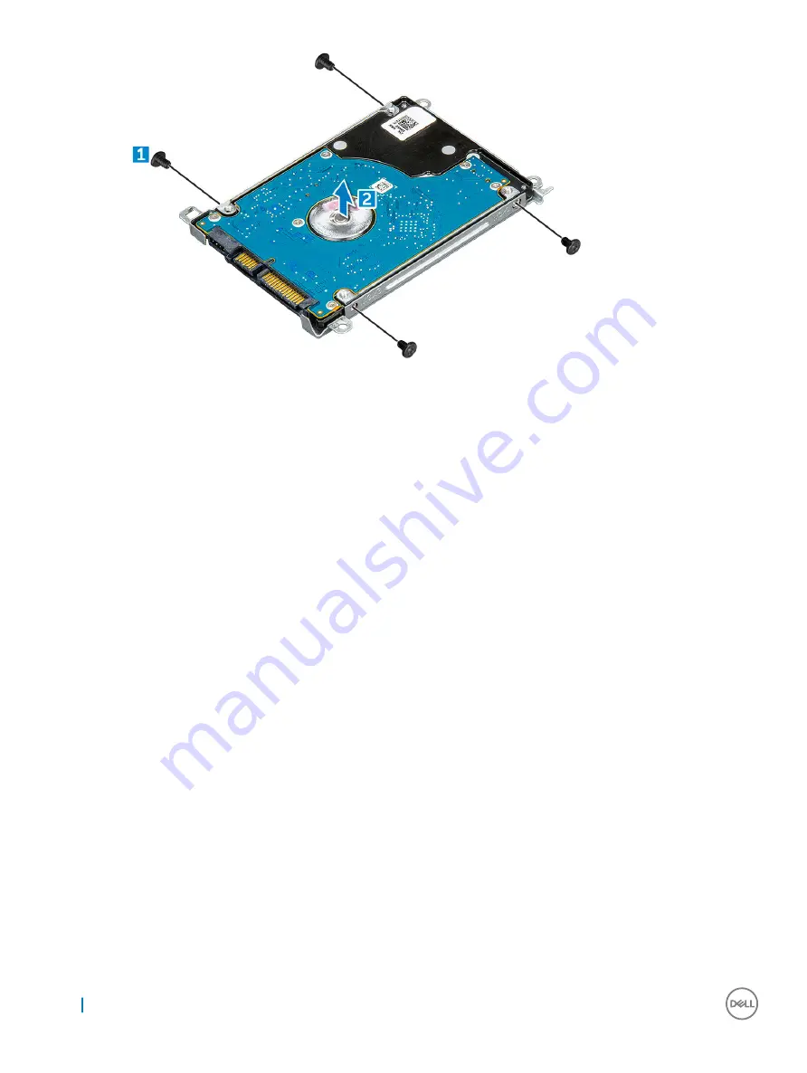
Tighten the M3xL3 screws to attach the metal bracket to the HDD.

Connect the HDD cable interposer.

Insert the HDD into the slot on the computer.

Tighten the M2xL3 screws to secure the HDD to the computer.

Connect the HDD cable to the system board.

Install the:

a

battery

b

base cover

c

microSD card

Follow the procedure in 

After working inside your computer

.

eMMC assembly

Removing Embedded Multimedia Card (eMMC) assembly

Follow the procedure in 

Before working inside your computer

.

Remove the:

a

microSD card

b

base cover

c

battery

Disconnect the interposer cable from the system board, remove the M2.0L3 screws that secure the bracket to the chassis and gently 
lift the eMM card out.

22

Removing and installing components

Summary of Contents for Latitude 3380

Page 1: ...Latitude 3380 Owner s Manual Regulatory Model P80G Regulatory Type P80G001 ...

Page 2: ...amage to hardware or loss of data and tells you how to avoid the problem WARNING A WARNING indicates a potential for property damage personal injury or death 2017 Dell Inc or its subsidiaries All rights reserved Dell EMC and other trademarks are trademarks of Dell Inc or its subsidiaries Other trademarks may be trademarks of their respective owners 2017 02 Rev A00 ...

Page 3: ...moving keyboard 11 Installing keyboard 15 WLAN Card 15 Removing WLAN 15 Installing WLAN card 16 Memory Module 16 Removing the memory module 16 Installing the memory module 17 Heat sink 17 Removing heat sink 17 Installing heat sink 18 System Fan 19 Removing system fan 19 Installing system fan 20 Hard disk drive HDD 20 Removing hard disk drive HDD 20 Installing hard disk drive HDD 22 eMMC assembly 2...

Page 4: ...Chipsets 36 Identifying the chipset in Device Manager on Windows 10 36 Intel HD Graphics 36 Display options 37 Identifying the display adapter 37 Changing the screen resolution 37 Adjusting brightness in Windows 10 37 Connecting to external display devices 37 DDR4 37 Memory features 39 Verifying system memory in Windows 10 39 Verifying system memory in system setup BIOS 39 Testing memory using ePS...

Page 5: ...in Windows 54 System and setup password 54 Assigning a system password and setup password 55 Deleting or changing an existing system and or setup password 55 5 Technical specifications 56 System specifications 56 Processor specifications 57 Memory specifications 57 Storage specifications 57 Audio specifications 57 Video specifications 58 Camera specifications 58 Communication specifications 58 Por...

Page 6: ...7 Contacting Dell 64 6 Contents ...

Page 7: ...bly tasks CAUTION Handle components and cards with care Do not touch the components or contacts on a card Hold a card by its edges or by its metal mounting bracket Hold a component such as a processor by its edges not by its pins CAUTION When you disconnect a cable pull on its connector or on its pull tab not on the cable itself Some cables have connectors with locking tabs if you are disconnectin...

Page 8: ...our computer After you complete any replacement procedure ensure you connect any external devices cards and cables before turning on your computer CAUTION To avoid damage to the computer use only the battery designed for this particular Dell computer Do not use batteries designed for other Dell computers 1 Replace the battery 2 Replace the base cover 3 Connect any external devices such as a port r...

Page 9: ...D card Removing microSD card 1 Press in on the microSD card to release it from the computer 2 Remove the microSD card from the computer Installing microSD card Slide the microSD card into its slot until it clicks into place Base Cover Removing base cover 1 Follow the procedure in Before working inside your computer 2 Remove the microSD card 3 To remove the base cover a Loosen the M2 5xL8 5 captive...

Page 10: ...rd 5 Follow the procedure in After working inside your computer Battery Removing battery 1 Follow the procedure in Before working inside your computer 2 Remove the a microSD card b base cover 3 To remove the battery a Disconnect the battery cable from the connector on the system board 1 b Remove the M2 0x3 0 screws that secure the battery to the computer 2 c Lift the battery away from the computer...

Page 11: ...ure the battery to the computer 4 Install the a base cover b microSD card 5 Follow the procedure in After working inside your computer Keyboard Removing keyboard 1 Follow the procedure in Before working inside your computer 2 Remove the a microSD card b base cover c battery 3 Disconnect the keyboard cable from the system board Removing and installing components 11 ...

Page 12: ...force to push out the keyboard through the two release holes Please exercise due caution NOTE Picture for representational purpose to show exact location of keyboard latches It is not necessary to remove the heat sink hard drive or system board in order to access the keyboard release holes 12 Removing and installing components ...

Page 13: ...5 Gently pry up the lower edge of the keyboard from the computer Removing and installing components 13 ...

Page 14: ...6 Remove the keyboard away from the computer 14 Removing and installing components ...

Page 15: ...rd cable on the system board 3 Install the a battery b base cover c microSD card 4 Follow the procedure in After working inside your computer WLAN Card Removing WLAN 1 Follow the procedure in Before working inside your computer 2 Remove the a microSD card b base cover c battery 3 To remove the WLAN Removing and installing components 15 ...

Page 16: ... Insert the WLAN card into its connector on the system board 2 Connect the two antenna cables to the WLAN card 3 Replace the metal bracket on the WLAN 4 Tighten the M2xL3 screw to secure the WLAN card and bracket to the system board 5 Install the a battery b base cover c microSD card 6 Follow the procedure in After working inside your computer Memory Module Removing the memory module 1 Follow the ...

Page 17: ...dule 1 Insert the memory module into its connector on the system board 2 Gently push the memory module until the latches snap it into place 3 Install the a battery b base cover c microSD card 4 Follow the procedure in After working inside your computer Heat sink Removing heat sink 1 Follow the procedure in Before working inside your computer 2 Remove the Removing and installing components 17 ...

Page 18: ...computer 5 Installing heat sink 1 Insert the heat sink into the slot on the computer 2 Tighten the M2 5x2 5 screws to secure the heat sink to the computer NOTE Follow the diagonal pattern to tighten the screws similar to the pattern followed to loosen the screws in Removing heat sink 3 Install the a battery b base cover c microSD card 4 Follow the procedure in After working inside your computer 18...

Page 19: ...y 3 To remove the system fan a Unroute the WLAN cable from the connector on the system board 1 b Pry out the cable from its hook 2 4 Disconnect the system fan connector from the system board 1 5 Remove the M2xL3 screws that secure the fan to the system board 2 6 Lift the system fan off the system board 3 Removing and installing components 19 ...

Page 20: ...se cover c microSD card 6 Follow the procedure in After working inside your computer Hard disk drive HDD Removing hard disk drive HDD 1 Follow the procedure in Before working inside your computer 2 Remove the a microSD card b base cover c battery 3 To remove the HDD a Disconnect the HDD cable from the system board 1 b Remove the M2xL3 screws that secure the HDD to the palmrest 2 c Lift the HDD fro...

Page 21: ...4 Disconnect the HDD cable interposer 5 Then remove the M3xL3 screws to detach the metal bracket from the HDD 1 Removing and installing components 21 ...

Page 22: ...ard 6 Install the a battery b base cover c microSD card 7 Follow the procedure in After working inside your computer eMMC assembly Removing Embedded Multimedia Card eMMC assembly 1 Follow the procedure in Before working inside your computer 2 Remove the a microSD card b base cover c battery 3 Disconnect the interposer cable from the system board remove the M2 0L3 screws that secure the bracket to ...

Page 23: ...4 Disconnect the hard drive interposer from the eMM card 5 Flip the hard drive bracket remove the screws M2 0 and take out the eMM card from the bracket Removing and installing components 23 ...

Page 24: ... 5 Follow the procedure in After working inside your computer DC In Board Removing DC in connector 1 Follow the procedure in Before working inside your computer 2 Remove the a microSD card b base cover c battery 3 To remove the DC in connector a Disconnect the DC in cable from its connector on the system board 1 b Remove the M2 5xL5 screw that secures the DC in connector to the display hinge 2 c L...

Page 25: ...ery b base cover c microSD card 5 Follow the procedure in After working inside your computer Audio board Removing the audio board 1 Follow the procedure in Before working inside your computer 2 Remove the a microSD card b base cover c battery 3 To remove the audio board a Disconnect the audio board cable from its connector on the system board 1 Removing and installing components 25 ...

Page 26: ...the computer 2 Tighten the M2xL3 screw to secure the audio board to the computer 3 Affix the cable adhesive to the computer 4 Reconnect the audio board cable to its connector on the system board 5 Install the a battery b base cover c microSD card 6 Follow the procedure in After working inside your computer Coin cell battery Removing the coin cell battery 1 Follow the procedure in Before working in...

Page 27: ... strong adhesive is used on the coin battery a bit of force is needed to peel up the battery from the palmrest Installing coin cell battery 1 Place the coin cell battery into the system 2 Route the battery cable under the plastic shields on the system 3 Connect the coin cell battery cable to the connector on the system board 4 Install the a battery b base cover c microSD card 5 Follow the procedur...

Page 28: ...on the system board 1 b Lift the speaker cable off from the cable guide 2 c Remove the adhesive tape that secures the speaker cable to the computer 3 NOTE Speakers are held down with adhesive tape as well as rubber grommets The rubber grommets will come up with the speaker assembly d Unroute the speaker cable from the routing channel 4 4 Remove the speakers from the computer 28 Removing and instal...

Page 29: ...Follow the procedure in After working inside your computer Display assembly Removing the display assembly NOTE This process is for both nontouch and touch LCDs 1 Follow the procedure in Before working inside your computer 2 Remove the a microSD card b base cover c battery d WLAN Card e DC IN board 3 Remove the screw that secures the metal bracket of the display cable 1 and remove it from the syste...

Page 30: ...4 Remove the M1 6xL2 screws 1 and lift the display assembly away from the computer 2 30 Removing and installing components ...

Page 31: ...b DC IN board c battery d base cover e microSD card 7 Follow the procedure in After working inside your computer System board Removing system board 1 Follow the procedure in Before working inside your computer 2 Remove the a microSD card b base cover c battery d WLAN card e memory module f heat sink g fan h DCin 3 Remove the screw that secures the metal bracket of the display cable 1 and remove it...

Page 32: ...cables and connectors a Audio board cable connector 1 b Audio board cable tape 2 c Speaker cable connector 3 d HDD cable connector 4 e Touchpad cable connector 5 f Keyboard cable connector 6 32 Removing and installing components ...

Page 33: ...5 Remove the M2xL3 screws 1 and lift the system board away from the computer 2 Removing and installing components 33 ...

Page 34: ...ble coin cell battery cable and the keyboard cables to their respective connectors 4 Connect the display cable to the connector 5 Place the metal bracket over the connector and tighten the M2xL3 screw to secure the display cable to the computer 6 Install the a DCin b fan c heat sink d memory module e WLAN card f battery g base cover h microSD card 7 Follow the procedure in After working inside you...

Page 35: ...ts worldwide However power connectors and power strips vary among countries Using an incompatible cable or improperly connecting the cable to the power strip or electrical outlet may cause fire or equipment damage Processors This laptop is shipped with the following processors Table 1 Intel Processor List 6th Generation Skylake Intel Core i3 6006U Processor 15W 3M cache 2 0GHz 7th Generation Kaby ...

Page 36: ...pen Resource Monitor Chipsets All laptops or notebooks communicate with the CPU through the chipset This laptop is shipped with the Intel Skylake and Intel Kabylake series chipset Identifying the chipset in Device Manager on Windows 10 1 Click inside the Cortana Search Box and type Control Panel and then click or press Enter on the keyboard for the appropriate search result 2 From the Control Pane...

Page 37: ... your computer to an external display device 1 Ensure that the projector is turned on and plug the projector cable into a video port on your computer 2 Press the Windows logo P key 3 Select one of the following modes PC screen only Duplicate Extend Second Screen only DDR4 DDR4 double data rate fourth generation memory is a higher speed successor to the DDR2 and DDR3 technologies and allows up to 5...

Page 38: ...d thickness DDR4 modules are slightly thicker than DDR3 to accommodate more signal layers Figure 2 Thickness difference Curved edge DDR4 modules feature a curved edge to help with insertion and alleviate stress on the PCB during memory installation Figure 3 Curved edge Memory Errors Memory errors on the system display the new ON FLASH FLASH or ON FLASH ON failure code If all memory fails the LCD d...

Page 39: ...ons after the Dell logo is displayed With keyboard Press F12 The PreBoot System Assessment PSA starts on your system NOTE If you wait too long and the operating system logo appears continue to wait until you see the desktop Turn off the laptop and try again Graphic options This laptop is shipped with the following graphics chipset Intel HD Graphics 610 Intel Corei3 6606U Intel HD graphics 520 Inte...

Page 40: ...le The topics below cover some of the most commonly asked questions regarding USB 3 0 USB 3 1 Gen 1 Speed Currently there are 3 speed modes defined by the latest USB 3 0 USB 3 1 Gen 1 specification They are Super Speed Hi Speed and Full Speed The new SuperSpeed mode has a transfer rate of 4 8Gbps While the specification retains Hi Speed and Full Speed USB mode commonly known as USB 2 0 and 1 1 res...

Page 41: ...previously weren t USB territory like external RAID storage systems Listed below are some of the available SuperSpeed USB 3 0 USB 3 1 Gen 1 products External Desktop USB 3 0 USB 3 1 Gen 1 Hard Drives Portable USB 3 0 USB 3 1 Gen 1 Hard Drives USB 3 0 USB 3 1 Gen 1 Drive Docks Adapters USB 3 0 USB 3 1 Gen 1 Flash Drives Readers USB 3 0 USB 3 1 Gen 1 Solid state Drives USB 3 0 USB 3 1 Gen 1 RAIDs Op...

Page 42: ... The hard drive is listed under Disk drives Identifying the hard drive in the BIOS 1 Turn on or restart your system 2 When the Dell logo appears perform the following action to enter the BIOS setup program With keyboard Tap F2 until the Entering BIOS setup message appears To enter the Boot selection menu tap F12 The hard drive is listed under the System Information under the General group HDMI 1 4...

Page 43: ...ng environment while delivering true HD quality Advantages of HDMI Quality HDMI transfers uncompressed digital audio and video for the highest crispest image quality Low cost HDMI provides the quality and functionality of a digital interface while also supporting uncompressed video formats in a simple cost effective manner Audio HDMI supports multiple audio formats from standard stereo to multicha...

Page 44: ...2 Select Camera from the apps list 3 If the Camera App is not available in the apps list search for it 44 Technology and components ...

Page 45: ...stem and setup password Boot Sequence Boot Sequence allows you to bypass the System Setup defined boot device order and boot directly to a specific device for example optical drive or hard drive During the Power on Self Test POST when the Dell logo appears you can Access System Setup by pressing F2 key Bring up the one time boot menu by pressing F12 key The one time boot menu displays the devices ...

Page 46: ...tup it is recommended that you write down the System Setup screen information for future reference CAUTION Unless you are an expert computer user do not change the settings for this program Certain changes can cause your computer to work incorrectly Accessing System Setup 1 Turn on or restart your computer 2 After the white Dell logo appears press F2 immediately The System Setup page is displayed ...

Page 47: ...e System Configuration screen options Option Description Drives Allows you to configure the SATA drives on board SATA 0 enabled by default eMMC System Default USB Configuration This is an optional feature This field configures the integrated USB controller If Boot Support is enabled the system is allowed to boot any type of USB Mass Storage Devices HDD memory key floppy If USB port is enabled devi...

Page 48: ...Description Admin Password Allows you to set change or delete the administrator admin password NOTE You must set the admin password before you set the system or hard drive password Deleting the admin password automatically deletes the system password and the hard drive password NOTE Successful password changes take effect immediately Default setting Not set System Password Allows you to set change...

Page 49: ...you to enable or disable This option controls whether this system allows BIOS updated via UEFI capsule update packages The options are Enable UEFI Capsule Firmware enabled by default TPM 2 0 Security Allows you to enable the Trusted Platform Module TPM during POST The options are TPM On enabled by default Clear PPI Bypass for Enable Commands enabled by default PPI Bypass for Disabled Commands Atte...

Page 50: ...ete Deletes the selected key Reset All Keys Resets to default setting Delete All Keys Deletes all the keys NOTE If you disable the Custom Mode all the changes made are erased and the keys restore to default settings Performance screen options Option Description Multi Core Support This field specifies whether the process has one or all cores enabled The performance of some applications improves wit...

Page 51: ...rom Standby NOTE This feature is only functional when the AC power adapter is connected If the AC power adapter is removed during Standby the system setup removes power from all the USB ports to conserve battery power Enable USB Wake Support Wake on Dell USB C dock Default setting The option is disabled Wake on WLAN Allows you to enable or disable the feature that powers on the computer from the O...

Page 52: ...le the Advanced Battery Charge Configuration option Sleep mode OS Automatic selection Force S3 enabled by default POST behavior screen options Option Description Adapter Warnings Allows you to enable or disable the system setup BIOS warning messages when you use certain power adapters Default setting Enable Adapter Warnings Numlock Enable Allows you to enable the Numlock option when the computer b...

Page 53: ...ata Wipe This field allows users to erase the data securely from all internal storage devices Option Wipe on Next boot is not enabled by default The following is list of devices affected Internal SATA HDD SSD Internal M 2 SATA SDD Internal M 2 PCIe SSD Internal eMMC BIOS Recovery This field allows you to recover from certain corrupted BIOS conditions from a recover file on the user primary hard dr...

Page 54: ...computer model and the Product Support page of your computer appears 6 Click Get drivers and click Drivers and Downloads The Drivers and Downloads section opens 7 Click Find it myself 8 Click BIOS to view the BIOS versions 9 Identify the latest BIOS file and click Download 10 Select your preferred download method in the Please select your download method below window click Download File The File D...

Page 55: ...mpts you to save the changes 5 Press Y to save the changes The computer reboots Deleting or changing an existing system and or setup password Ensure that the Password Status is Unlocked in the System Setup before attempting to delete or change the existing System and or Setup password You cannot delete or change an existing System or Setup password if the Password Status is Locked To enter the Sys...

Page 56: ...ecifications Camera specifications Communication specifications Port and connector specifications Display specifications Keyboard specifications Touchpad specifications Battery specifications AC adapter specifications Physical specifications Environmental specifications System specifications Feature Specification Chipset Intel Skylake and Kabylake integrated with processor DRAM bus width 64 bit Fl...

Page 57: ...4 SDRAM Speed 2133 MHz Minimum memory 4 GB Maximum memory 8 GB Storage specifications Drive Type Capacity 500 GB 2 5 HDD 7200 RPM 500 GB SSD Capacity 128 GB and 256 GB Drive Type 128 GB 256 GB SSD 2 5 7 mm SATA Class 20 Audio specifications Feature Specification Types High definition audio Controller Realtek ALC3246 Stereo conversion Stereo conversion 16 20 24 bit analog to digital and digital to ...

Page 58: ...280 x 720 pixels Diagonal viewing angle 74 Communication specifications Features Specification Network adapter 10 100 1000 Mb s Ethernet RJ 45 Wireless Intel Dual Band Wireless AC 7265 802 11AC 2x2 Wi Fi BT 4 2 LE M 2 Wireless Card Qualcomm DW1820 QCA61x4A 802 11ac Dual Band 2x2 Wireless Adapter Bluetooth 4 1 LE M 2 Wireless Card optional 4G LTE Mobile Broadband Port and connector specifications F...

Page 59: ...Anti Glare non touch 13 3 HD 16 9 1366 x 768 Touch with Corning Gorilla Glass NBT Diagonal 13 3 inches Maximum resolution 1366 x 768 Maximum brightness 200 nits Refresh rate 60 Hz Maximum viewing angles horizontal HD 40 40 degrees Maximum viewing angles vertical HD 10 30 degrees Pixel pitch 0 2148 mm Keyboard specifications Feature Specification Number of keys United States 82 keys United Kingdom ...

Page 60: ... 50 C 32 F to 122 F Discharge 0 C to 70 C 32 F to 158 F Operating 0 C to 35 C 32 F to 95 F Non operating 40 C to 65 C 40 F to 149 F Coin cell battery 3 V CR2032 lithium coin cell AC adapter specifications Feature Specification Type E4 65 W 65 Watt AC Adapter E5 65 W Rugged India only E4 65 W HF BFR PVC Free Dell Portable Power Companion 12000 mAh PW7015M Power Companion 43 Wh Dura Ace Dell Portabl...

Page 61: ... based on a typical configuration and may vary based on the actual configuration Environmental specifications Temperature Specifications Operating 0 C to 35 C 32 F to 95 F Storage 40 C to 65 C 40 F to 149 F Relative humidity maximum Specifications Operating 10 to 90 non condensing Storage 5 to 95 non condensing Altitude maximum Specifications Operating 0 m to 3048 m 0 ft to 10 000 ft Non operating...

Page 62: ...d Key Databases System Logs The following items may or may not reset based on your custom BIOS setting selections The Boot List Enable Legacy OROMs Secure Boot Enable Allow BIOS Downgrade Enhanced Pre Boot System Assessment ePSA diagnostics The ePSA diagnostics also known as system diagnostics performs a complete check of your hardware The ePSA is embedded with the BIOS and is launched by the BIOS...

Page 63: ...ion The Enhanced Pre boot System Assessment window is displayed 4 Click the arrow key at the bottom left corner Diagnostics front page is displayed 5 Press the arrow in the lower right corner to go to the page listing The items detected are listed 6 To run a diagnostic test on a specific device press Esc and click Yes to stop the diagnostic test 7 Select the device from the left pane and click Run...

Page 64: ... service options Availability varies by country and product and some services may not be available in your area To contact Dell for sales technical support or customer service issues 1 Go to Dell com support 2 Select your support category 3 Verify your country or region in the Choose a Country Region drop down list at the bottom of the page 4 Select the appropriate service or support link based on...

Reviews: