background image

Safety instructions

Use the following safety guidelines to protect your computer from potential damage and to ensure your personal safety. Unless otherwise 
noted, each procedure included in this document assumes that the following conditions exist:

You have read the safety information that shipped with your computer.

A component can be replaced or, if purchased separately, installed by performing the removal procedure in reverse order.

NOTE: 

Disconnect all power sources before opening the computer cover or panels. After you finish working inside the 

computer, replace all covers, panels, and screws before connecting to the power source.

WARNING: 

Before working inside your computer, read the safety information that shipped with your computer. For 

additional safety best practices information, see the 

Regulatory Compliance Homepage

CAUTION: 

Many repairs may only be done by a certified service technician. You should only perform troubleshooting and 

simple repairs as authorized in your product documentation, or as directed by the online or telephone service and 
support team. Damage due to servicing that is not authorized by Dell is not covered by your warranty. Read and follow 
the safety instructions that came with the product.

CAUTION: 

To avoid electrostatic discharge, ground yourself by using a wrist grounding strap or by periodically touching 

an unpainted metal surface at the same time as touching a connector on the back of the computer.

CAUTION: 

Handle components and cards with care. Do not touch the components or contacts on a card. Hold a card by 

its edges or by its metal mounting bracket. Hold a component such as a processor by its edges, not by its pins.

CAUTION: 

When you disconnect a cable, pull on its connector or on its pull-tab, not on the cable itself. Some cables 

have connectors with locking tabs; if you are disconnecting this type of cable, press in on the locking tabs before you 
disconnect the cable. As you pull connectors apart, keep them evenly aligned to avoid bending any connector pins. Also, 
before you connect a cable, ensure that both connectors are correctly oriented and aligned.

NOTE: 

The color of your computer and certain components may appear differently than shown in this document.

Topics:

Before working inside your computer

Electrostatic discharge—ESD protection

ESD field service kit 

Transporting sensitive components

After working inside your computer

Before working inside your computer

To avoid damaging your computer, perform the following steps before you begin working inside the computer.

1. Ensure that you follow the 

Safety Instruction

.

2. Ensure that your work surface is flat and clean to prevent the computer cover from being scratched.
3. Turn off your computer.
4. Disconnect all network cables from the computer.

CAUTION: 

To disconnect a network cable, first unplug the cable from your computer and then unplug the cable from 

the network device.

5. Disconnect your computer and all attached devices from their electrical outlets.
6. Press and hold the power button while the computer is unplugged to ground the system board.

NOTE: 

To avoid electrostatic discharge, ground yourself by using a wrist grounding strap or by periodically touching 

an unpainted metal surface at the same time as touching a connector on the back of the computer.

1

6

Safety instructions

Summary of Contents for Inspiron 7591

Page 1: ...Inspiron 7591 Service Manual Regulatory Model P83F Regulatory Type P83F001 ...

Page 2: ...age to hardware or loss of data and tells you how to avoid the problem WARNING A WARNING indicates a potential for property damage personal injury or death 2018 2019 Dell Inc or its subsidiaries All rights reserved Dell EMC and other trademarks are trademarks of Dell Inc or its subsidiaries Other trademarks may be trademarks of their respective owners 2019 07 Rev A01 ...

Page 3: ...ttery 15 Memory modules 16 Removing the memory modules 16 Installing the memory modules 17 WLAN card 18 Removing the WLAN card 18 Installing the WLAN card 18 Solid state drive 19 Removing the M 2 2280 solid state drive 19 Installing the M 2 2280 solid state drive 20 Removing the M 2 2230 solid state drive 21 Installing the M 2 2230 solid state drive 22 Removing the M 2 2280 PCIe solid state drive ...

Page 4: ...3 Removing the touchpad 43 Installing the touchpad 44 Display assembly 45 Removing the display assembly 45 Installing the display assembly 48 Display bezel 49 Removing the display bezel 49 Installing the display bezel 50 System board 51 Removing the system board 51 Installing the system board 54 Palm rest and keyboard assembly 58 Removing the palm rest and keyboard assembly 58 Installing the palm ...

Page 5: ... diagnostics 68 Running the ePSA diagnostics 68 System diagnostic lights 68 Recovering the operating system 69 Enabling Intel Optane memory 69 Disabling Intel Optane memory 70 Flashing BIOS USB key 70 Flashing the BIOS 70 Flea power release 70 Wi Fi power cycle 71 6 Getting help and contacting Dell 72 Contents 5 ...

Page 6: ...card by its edges or by its metal mounting bracket Hold a component such as a processor by its edges not by its pins CAUTION When you disconnect a cable pull on its connector or on its pull tab not on the cable itself Some cables have connectors with locking tabs if you are disconnecting this type of cable press in on the locking tabs before you disconnect the cable As you pull connectors apart ke...

Page 7: ...rmittent also called latent or walking wounded failure Perform the following steps to prevent ESD damage Use a wired ESD wrist strap that is properly grounded The use of wireless anti static straps is no longer allowed they do not provide adequate protection Touching the chassis before handling parts does not ensure adequate ESD protection on parts with increased sensitivity to ESD damage Handle a...

Page 8: ...urface and parts should never be placed on top of the ESD bag because only the inside of the bag is shielded Always place parts in your hand on the ESD mat in the system or inside an anti static bag Transporting Sensitive Components When transporting ESD sensitive components such as replacement parts or parts to be returned to Dell it is critical to place these parts in anti static bags for safe t...

Page 9: ...d to such surface when replacing a component NOTE Screw color may vary with the configuration ordered Table 1 Screw list Component Secured to Screw type Quantity Screw image Base cover Palm rest and keyboard assembly M2x5 5 6 Cell Battery Palm rest and keyboard assembly M2x4 7 3 Cell battery Palm rest and keyboard assembly M2x4 4 Hard drive NOTE The hard drive is available only in computers shippe...

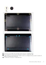
Page 10: ... Palm rest and keyboard assembly M2x4 1 USB Type C bracket System board M2x4 2 Touchpad bracket Palm rest and keyboard assembly M2x3 3 Touchpad Palm rest and keyboard assembly M1 6x2 2 WLAN card bracket WLAN card M2x4 1 System board Palm rest and keyboard assembly M2x4 6 Base cover Removing the base cover 1 Follow the procedure in Before working inside your computer The figure indicates the locati...

Page 11: ...secure the base cover to the palm rest and keyboard assembly 3 Pry open the base cover starting from the top center edge of the palm rest and keyboard assembly and follow the guidance line indicated in the image to remove the base cover 4 Lift the base cover off the palm rest and keyboard assembly Removing and installing components 11 ...

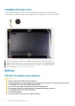
Page 12: ...r to the palm rest and keyboard assembly 1 Follow the procedure in After working inside your computer Battery Lithium ion battery precautions CAUTION Exercise caution when handling Lithium ion batteries Discharge the battery as much as possible before removing it from the system This can be done by disconnecting the AC adapter from the system to allow the battery to drain Do not crush drop mutilat...

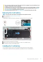
Page 13: ...y NOTE The battery type in your computer varies depending on the configuration ordered 1 Follow the procedure in Before working inside your computer 2 Remove the base cover The figure indicates the location of the battery and provides a visual representation of the removal procedure 1 Disconnect the battery cable from the system board 2 Remove the four screws M2x4 that secure the battery to the pa...

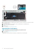
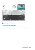
Page 14: ...nnect the battery cable to the system board 1 Install the base cover 2 Follow the procedure in After working inside your computer Removing the 6 cell battery NOTE The battery type in your computer varies depending on the configuration ordered 1 Follow the procedure in Before working inside your computer 2 Remove the base cover The figure indicates the location of the battery and provides a visual ...

Page 15: ... Lift the battery off the palm rest and keyboard assembly Installing the 6 cell battery If you are replacing a component remove the existing component before performing the installation procedure The figure indicates the location of the battery and provides a visual representation of the installation procedure Removing and installing components 15 ...

Page 16: ...rd assembly 3 Connect the battery cable to the system board 1 Install the base cover 2 Follow the procedure in After working inside your computer Memory modules Removing the memory modules 1 Follow the procedure in Before working inside your computer 2 Remove the base cover 3 Disconnect the battery cable The figure indicates the location of the memory module and provides a visual representation of...

Page 17: ...ling the memory modules If you are replacing a component remove the existing component before performing the installation procedure The figure indicates the location of the memory module and provides a visual representation of the installation procedure 1 Lift the mylar and align the notch on the memory module with the tab on the memory module slot 2 Slide the memory module firmly into the slot at...

Page 18: ...e location of the WLAN card and provides a visual representation of the removal procedure 1 Remove the screw M2x4 that secures the WLAN card bracket to the WLAN card 2 Remove the WLAN card bracket from the WLAN card 3 Disconnect the antenna cables from the WLAN card 4 Slide and remove the WLAN card from the WLAN card slot Installing the WLAN card If you are replacing a component remove the existin...

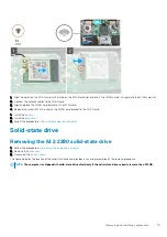
Page 19: ...nstall the base cover 3 Follow the procedure in After working inside your computer Solid state drive Removing the M 2 2280 solid state drive 1 Follow the procedure in Before working inside your computer 2 Remove the base cover 3 Disconnect the battery cable The figure indicates the location of the solid state drive and provides a visual representation of the removal procedure NOTE The computer is ...

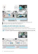
Page 20: ...talling the M 2 2280 solid state drive If you are replacing a component remove the existing component before performing the installation procedure The figure indicates the location of the solid state drive bracket and provides a visual representation of the bracket alignment procedure to accommodate the M 2 2280 solid state drive NOTE The computer is shipped with solid state drive shield only if t...

Page 21: ...e solid state drive slot with the slot on the solid state drive bracket 5 Replace the two screws M2x4 that secure the solid state drive module shield to the palm rest and keyboard assembly 1 Connect the battery cable 2 Install the base cover 3 Follow the procedure in After working inside your computer Removing the M 2 2230 solid state drive 1 Follow the procedure in Before working inside your comp...

Page 22: ...eplacing a component remove the existing component before performing the installation procedure The figure indicates the location of the solid state drive bracket and provides a visual representation of the bracket alignment procedure to accommodate the M 2 2230 solid state drive The figure indicates the location of the M 2 2230 solid state drive and provides a visual representation of the install...

Page 23: ...the solid state drive module to the palm rest and keyboard assembly 1 Connect the battery cable 2 Install the base cover 3 Follow the procedure in After working inside your computer Removing the M 2 2280 PCIe solid state drive 1 Follow the procedure in Before working inside your computer 2 Remove the base cover 3 Disconnect the battery cable The figure indicates the location of the M 2 2280 PCIe s...

Page 24: ...before performing the installation procedure The figure indicates the location of the M 2 2280 PCIe solid state drive and provides a visual representation of the installation procedure 1 Align the notch on the solid state drive module with the tab on the solid state drive slot 2 Slide the solid state drive module firmly into the solid state drive slot at an angle 3 Replace the screw M2x4 that secu...

Page 25: ...e 1 Follow the procedure in Before working inside your computer 2 Remove the base cover 3 Disconnect the battery cable The figure indicates the location of the hard drive and provides a visual representation of the removal procedure NOTE The hard drive is available only in computers shipped with 3 cell battery Removing and installing components 25 ...

Page 26: ...ive assembly 5 Remove the four screws M3x3 that secure the hard drive bracket to the hard drive 6 Lift the hard drive off of the hard drive bracket Installing the hard drive If you are replacing a component remove the existing component before performing the installation procedure The figure indicates the location of the hard drive and provides a visual representation of the installation procedure...

Page 27: ...keyboard assembly 5 Replace the three screws M2x4 that secure the hard drive assembly to the palm rest and keyboard assembly 6 Connect the hard drive cable to the system board 1 Connect the battery cable 2 Install the base cover 3 Follow the procedure in After working inside your computer Speakers Removing the speakers 1 Follow the procedure in Before working inside your computer 2 Remove the base...

Page 28: ...he rubber grommets before lifting the speakers 3 Lift the speakers along with the cable off the palm rest and keyboard assembly Installing the speakers If you are replacing a component remove the existing component before performing the installation procedure The figure indicates the location of the speakers and provides a visual representation of the installation procedure 28 Removing and install...

Page 29: ...e to the system board 1 Install the battery 2 Install the base cover 3 Follow the procedure in After working inside your computer Graphics Processing Unit GPU fan Removing the GPU fan 1 Follow the procedure in Before working inside your computer 2 Remove the base cover 3 Remove the battery The figure indicates the location of the GPU fan and provides a visual representation of the removal procedur...

Page 30: ... fan If you are replacing a component remove the existing component before performing the installation procedure The figure indicates the location of the GPU fan and provides a visual representation of the installation procedure 1 Slide and place the GPU fan on the palm rest and keyboard assembly 2 Align the screw holes on the GPU fan with the screw holes on the palm rest and keyboard assembly 30 ...

Page 31: ...ndicates the location of the CPU fan and provides a visual representation of the removal procedure 1 Remove the two M2x4 screws that secure the CPU fan to the palm rest and keyboard assembly 2 Disconnect the CPU fan cable from the system board 3 Slide and lift the CPU fan off the palm rest and keyboard assembly Installing the CPU fan If you are replacing a component remove the existing component b...

Page 32: ...he battery 2 Install the base cover 3 Follow the procedure in After working inside your computer Heat sink Removing the heat sink UMA NOTE The heat sink type in your computer varies depending on the configuration ordered 1 Follow the procedure in Before working inside your computer 2 Remove the base cover 3 Remove the battery 4 Remove the GPU fan 5 Remove the CPU fan The figure indicates the locat...

Page 33: ...mponent before performing the installation procedure The figure indicates the location of the heat sink and provides a visual representation of the installation procedure 1 Place the heat sink on the system board and align the screw holes on the heat sink with the screw holes on the system board 2 In sequential order as indicated on the heat sink tighten the four captive screws that secure the hea...

Page 34: ...an The figure indicates the location of the heat sink and provides a visual representation of the removal procedure 1 In sequential order as indicated on the heat sink loosen the seven captive screws that secure the heat sink to the system board 2 Lift and remove the heat sink off the system board Installing the heat sink discrete If you are replacing a component remove the existing component befo...

Page 35: ...the procedure in After working inside your computer Coin cell battery Removing the coin cell battery 1 Follow the procedure in Before working inside your computer 2 Remove the base cover 3 Remove the battery NOTE Removing the coin cell battery resets the BIOS setup program s settings to default It is recommended that you note the BIOS setup program s settings before removing the coin cell battery ...

Page 36: ...ard assembly Installing the coin cell battery If you are replacing a component remove the existing component before performing the installation procedure The figure indicates the location of the coin cell battery and provides a visual representation of the installation procedure 36 Removing and installing components ...

Page 37: ...stall the base cover 3 Follow the procedure in After working inside your computer I O board Removing the I O board 1 Follow the procedure in Before working inside your computer 2 Remove the base cover 3 Remove the battery 4 Remove the GPU fan The figure indicates the location of the I O board and provides a visual representation of the removal procedure Removing and installing components 37 ...

Page 38: ...ee screws M2x3 that secure the I O board to the palm rest and keyboard assembly 5 Lift the I O board off the palm rest and keyboard assembly Installing the I O board If you are replacing a component remove the existing component before performing the installation procedure The figure indicates the location of the I O board and provides a visual representation of the installation procedure 38 Remov...

Page 39: ... rest and keyboard assembly 4 Connect the coin cell battery cable to the I O board 5 Connect the fingerprint reader cable to the I O board and close the latch to secure the cable 6 Connect the I O board cable to the I O board and close the latch to secure the cable 1 Install the GPU fan 2 Install the battery 3 Install the base cover 4 Follow the procedure in After working inside your computer Remo...

Page 40: ...ure 1 Remove the two screws M1 2x2 that secure the power button with optional fingerprint reader to the palm rest and keyboard assembly 2 Lift the power button with optional fingerprint reader along with the fingerprint reader cable off the palm rest and keyboard assembly Installing the power button with optional fingerprint reader If you are replacing a component remove the existing component bef...

Page 41: ...ard 2 Install the GPU fan 3 Install the WLAN card 4 Install the battery 5 Install the base cover 6 Follow the procedure in After working inside your computer Power adapter port Removing the power adapter port 1 Follow the procedure in Before working inside your computer 2 Remove the base cover 3 Remove the battery The figure indicates the location of the power adapter port and provides a visual re...

Page 42: ... Disconnect the power adapter port cable from the system board 5 Lift the power adapter port along with its cable off the palm rest and keyboard assembly Installing the power adapter port If you are replacing a component remove the existing component before performing the installation procedure The figure indicates the location of the power adapter port and provides a visual representation of the ...

Page 43: ...the left display hinge to the system board 1 Install the battery 2 Install the base cover 3 Follow the procedure in After working inside your computer Touchpad Removing the touchpad 1 Follow the procedure in Before working inside your computer 2 Remove the base cover 3 Remove the battery 4 Remove the speakers The figure indicates the location of the touchpad and provides a visual representation of...

Page 44: ...the two M1 6x2 screws that secure the touchpad to the palm rest and keyboard assembly 5 Lift the touchpad along with the cable off the palm rest and keyboard assembly Installing the touchpad If you are replacing a component remove the existing component before performing the installation procedure The figure indicates the location of the component and provides a visual representation of the instal...

Page 45: ...pad bracket into the slot on the palm rest and keyboard assembly 5 Replace the three M2x3 screws that secure the touchpad bracket to the palm rest and keyboard assembly 1 Install the speakers 2 Install the battery 3 Install the base cover 4 Follow the procedure in After working inside your computer Display assembly Removing the display assembly 1 Follow the procedure in Before working inside your ...

Page 46: ...The figure indicates the location of the display assembly and provides a visual representation of the removal procedure 46 Removing and installing components ...

Page 47: ...splay cable from the system board 4 Remove the three screws M2 5x5 that secure the left display hinge to the system board 5 Remove the three screws M2 5x5 that secure the right display hinge to the system board 6 Open the display hinges at an angle of 90 degrees 7 Remove the palm rest and keyboard assembly off the display assembly Removing and installing components 47 ...

Page 48: ...acing a component remove the existing component before performing the installation procedure The figure indicates the location of the component and provides a visual representation of the installation procedure 48 Removing and installing components ...

Page 49: ...5x5 that secure the right display hinge to the system board 6 Connect the display cable on to the connector on the system board and adhere the tape to the system board 1 Install the WLAN card 2 Install the battery 3 Install the base cover 4 Follow the procedure in After working inside your computer Display bezel Removing the display bezel 1 Follow the procedure in Before working inside your comput...

Page 50: ...lay back cover and antenna assembly 2 Remove the display bezel off the display back cover and antenna assembly Installing the display bezel If you are replacing a component remove the existing component before performing the installation procedure The figure indicates the location of the display bezel and provides a visual representation of the installation procedure 50 Removing and installing com...

Page 51: ... After working inside your computer System board Removing the system board 1 Follow the procedure in Before working inside your computer 2 Remove the base cover 3 Remove the battery 4 Remove the M 2 2280 solid state drive 5 Remove the M 2 2230 solid state drive 6 Remove the WLAN card 7 Remove the GPU fan 8 Remove the CPU fan 9 Remove the heat sink 10 Remove the memory module 11 Remove the display ...

Page 52: ...The figure indicates the location of the system board and provides a visual representation of the removal procedure 52 Removing and installing components ...

Page 53: ...Removing and installing components 53 ...

Page 54: ...the system board 8 Remove the two screws M2x5 that secure the USB Type C port bracket to the system board 9 Remove the six screws M2x4 that secure the system board to the palm rest and keyboard assembly 10 Gently release the ports on the system board from the slots on the palm rest and keyboard assembly and lift the system board off the palm rest and keyboard assembly Installing the system board I...

Page 55: ...Removing and installing components 55 ...

Page 56: ...56 Removing and installing components ...

Page 57: ...cklight cable to the system board and close the latch to secure the cable 7 Connect the touchpad cable to the system board and close the latch to secure the cable 8 Connect the speaker cable to the system board 9 Connect the power adapter cable to the system board 10 Connect the I O board cable to the system board and close the latch to secure the cable 1 Install the display assembly 2 Install the...

Page 58: ...14 Remove the system board NOTE The system board can be removed along with the heat sink The figure indicates the location of the palm rest and keyboard assembly and provides a visual representation of the removal procedure After performing the steps in the pre requisites we are left with the palm rest and keyboard assembly Installing the palm rest and keyboard assembly If you are replacing a comp...

Page 59: ...power button with fingerprint reader 5 Install the I O board 6 Install the display assembly 7 Install the speakers 8 Install the CPU fan 9 Install the GPU fan 10 Install the hard drive 11 Install the WLAN card 12 Install the battery 13 Install the base cover 14 Follow the procedure in After working inside your computer Removing and installing components 59 ...

Page 60: ...l com support Intel Trusted Execution Engine Interface In the Device Manager check if the Intel Trusted Execution Engine Interface driver is installed Install the driver update from www dell com support Intel Virtual Button driver In the Device Manager check if the Intel Virtual Button driver is installed Install the driver updates from www dell com support Wireless and Bluetooth drivers In the De...

Page 61: ...able option such as the user password type of hard drive installed and enabling or disabling base devices Entering BIOS setup program 1 Turn on or restart your computer 2 During POST when the DELL logo is displayed watch for the F2 prompt to appear and then press F2 immediately NOTE The F2 prompt indicates that the keyboard is initialized This prompt can appear very quickly so you must watch for i...

Page 62: ...ess the System Setup screen System setup options NOTE Depending on this computer and its installed devices the items listed in this section may or may not appear Table 2 System setup options System information menu General System Information System Information BIOS Version Displays the BIOS version number Service Tag Displays the Service Tag of the computer Asset Tag Displays the Asset Tag of the ...

Page 63: ...Panel Type Displays the Panel Type of the computer Native Resolution Displays the native resolution of the computer Audio Controller Displays the audio controller information of the computer Wi Fi Device Displays the wireless device information of the computer Bluetooth Device Displays the bluetooth device information of the computer Battery Information Displays the battery health information Boot...

Page 64: ...f characters allowed for Admin and System passwords Password Bypass Bypass the System Boot Password and the internal HDD password prompts during a system restart Password Change Enable or disable changes to the System and Hard Disk passwords when an administrator password is set Non Admin Setup Changes Determines whether changes to the setup option are permitted when an administrator password is s...

Page 65: ...d Shift Technology Auto On Time Enable to set the computer to turn on automatically every day or on a preselected date and time This option can be configured only if the Auto On Time is set to Everyday Weekdays or Selected Days Default Disabled USB Wake Support Enable the USB devices to wake the computer from Standby Peak Shift Enable or disable the minimal usage of AC power at times of peak deman...

Page 66: ...m Asset Tag BIOS Downgrade Control flashing of the system firmware to previous revisions BIOS Recovery Enable the user to recover from certain corrupted BIOS conditions from a recovery file on the user primary hard drive or an external USB key Table 11 System setup options System Logs menu System Logs BIOS Events Display BIOS events Thermal Events Display Thermal events Power Events Display Power ...

Page 67: ...r the system or BIOS passwords contact Dell technical support as described at www dell com contactdell NOTE For information on how to reset Windows or application passwords refer to the documentation accompanying Windows or your application System setup 67 ...

Page 68: ...ont page is displayed 5 Click the arrow in the lower right corner to go to the page listing The items detected are listed 6 To run a diagnostic test on a specific device press Esc and click Yes to stop the diagnostic test 7 Select the device from the left pane and click Run Tests 8 If there are any issues error codes are displayed Note the error code and validation number and contact Dell System d...

Page 69: ...l Dell computers installed with Windows 10 operating system It consists of tools to diagnose and troubleshoot issues that may occur before your computer boots to the operating system It enables you to diagnose hardware issues repair your computer back up your files or restore your computer to its factory state You can also download it from the Dell Support site to troubleshoot and fix your compute...

Page 70: ...table USB drive 4 Connect the bootable USB drive to the computer that needs the BIOS update 5 Restart the computer and press F12 when the Dell logo is displayed on the screen 6 Boot to the USB drive from the One Time Boot Menu 7 Type the BIOS setup program filename and press Enter 8 The BIOS Update Utility appears Follow the instructions on the screen to complete the BIOS update Flashing the BIOS ...

Page 71: ...ue to Wi Fi connectivity issues a Wi Fi power cycle procedure may be performed The following procedure provides the instructions on how to conduct a Wi Fi power cycle NOTE Some ISPs Internet Service Providers provide a modem router combo device 1 Turn off your computer 2 Turn off the modem 3 Turn off the wireless router 4 Wait for 30 seconds 5 Turn on the wireless router 6 Turn on the modem 7 Turn...

Page 72: ... the related articles Learn and know the following information about your product Product specifications Operating system Setting up and using your product Data backup Troubleshooting and diagnostics Factory and system restore BIOS information See Me and My Dell at www dell com support manuals To locate the Me and My Dell relevant to your product identify your product through one of the following ...

Reviews: