background image

Removing and Replacing Parts

4-57

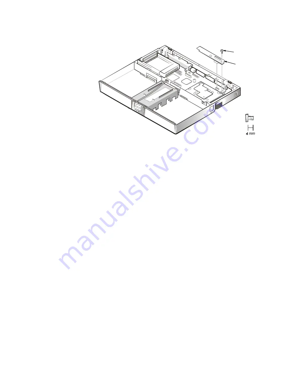
/9'6%RDUG

This section provides the removal procedure for the LVDS board.

)LJXUH/9'6%RDUG5HPRYDO

To remove the LVDS board, follow these steps (see Figure 4-38):

1.

Remove the 4-mm screw securing the LVDS board.

2. Gently pull the LVDS board off of connectors JP9 and JP8 on the system 

board. Do not rock the board to remove it, because this may damage the 
connectors. 

4-mm screw

LVDS board

Summary of Contents for Inspiron 7000

Page 1: ...Thank you for purchasing this Factory Service Manual CD DVD from servicemanuals4u com Please check out our eBay auctions for more great deals on Factory Service Manuals servicemanuals4u ...

Page 2: ...ZZZ GHOO FRP HOO QVSLURQ 6 59 0 18 ...

Page 3: ...ron is a trademark of Dell Computer Corporation MS DOS is a registered trademark of Microsoft Corporation Intel and Pentium are registered trademarks and MMX is a trademark of Intel Corporation IBM is a registered trademark of International Business Machines Corporation Other trademarks and trade names may be used in this document to refer to either the entities claiming the marks and names or the...

Page 4: ... Specifications 1 8 KDSWHU QLWLDO 3URFHGXUHV Initial User Contact 2 1 Visual Inspection 2 2 Observing the Boot Routine 2 4 Eliminating Resource Conflicts 2 5 Getting Help 2 5 KDSWHU HHS RGHV DQG UURU 0HVVDJHV POST Beep Codes 3 1 System Error Messages 3 2 Running the Dell Diagnostics 3 4 KDSWHU 5HPRYLQJ DQG 5HSODFLQJ 3DUWV Recommended Tools 4 1 Screw Identification and Tightening 4 2 Precautionary ...

Page 5: ... 4 50 Speakers 4 52 Base Assembly and Components 4 53 PC Card Heat Sink 4 54 Heat Exchanger Fan 4 55 DC DC Board 4 56 LVDS Board 4 57 Processor Board and Memory Module 4 58 Hinge Saddles 4 60 RJ 11 Card 4 61 System Board 4 62 PC Card Cage 4 63 Audio Card and Audio Thermal Shield 4 64 Latch Assembly 4 65 LJXUHV Figure 1 1 Front View 1 2 Figure 1 2 Back View 1 3 Figure 1 3 Indicator Panel above Keyb...

Page 6: ... 23 Modem Removal 4 35 Figure 4 24 Display Assembly Removal 4 37 Figure 4 25 Front Bezel Removal 4 38 Figure 4 26 13 3 Inch LCD Panel Removal 4 39 Figure 4 27 13 3 Inch LCD Brackets and Carrier Tray Removal 4 41 Figure 4 28 14 1 Inch LCD Panel Removal 4 42 Figure 4 29 MPEG 2 Card Removal 4 45 Figure 4 30 Palmrest Assembly Removal 4 46 Figure 4 31 IR Board Removal 4 48 Figure 4 32 Hard Disk Drive H...

Page 7: ...1 Interrupt Assignments 1 7 Table 1 2 Technical Specifications 1 8 Table 3 1 POST Beep Codes 3 2 Table 3 2 System Error Messages 3 2 Table 4 1 Factory Repair Parts and Assemblies 4 15 Table 4 2 Screw Location Template 4 31 ...

Page 8: ...ix ...

Page 9: ...dures and instructions on using the Dell diagnostics to test the computer system DUQLQJV DXWLRQV DQG 1RWHV Throughout this manual there may be blocks of text printed in bold type or in italic type These blocks are warnings cautions and notes and they are used as follows 51 1 51 1 LQGLFDWHV WKH SRWHQWLDO IRU ERGLO KDUP DQG SURYLGHV LQVWUXFWLRQV IRU KRZ WR DYRLG WKH SUREOHP 87 21 87 21 LQGLFDWHV HLW...

Page 10: ...XGA active matrix TFT LCD 6 VWHP HDWXUHV In addition to the standard features found in IBM compatible portable comput ers the Dell Inspiron 7000 computers include the following new and or advanced features A minimum of 32 MB of SDRAM on the system board The memory capac ity can be increased up to 192 MB by increasing the SDRAM on the system board to 64 MB and or by installing 32 or 64 MB 3 3 V mem...

Page 11: ...rs keyboards joy sticks and computer speakers USB devices are hot pluggable meaning that they can be connected and disconnected while the system is running PCI docking connector for full port replication Kensington Lock which secures the notebook 3K VLFDO HVFULSWLRQ Figures 1 1 and 1 2 illustrate front and back views of the Inspiron 7000 LJXUH URQW 9LHZ display speaker touch pad buttons 2 indicato...

Page 12: ...on Press Scroll Lock to turn this feature on or off LJXUH QGLFDWRU 3DQHO DERYH H ERDUG Five additional status lights are located on the front of the unit three in the indicator panel below the display latch and two on the left side see Figure 1 4 System power Solid green light when the system is on blinking green light when system is in suspend state PC Card slots serial connector monitor connecto...

Page 13: ...first reached Floppy disk drive activity Blinking green light as the drive is being accessed CD ROM or DVD ROM drive activity Blinking green light as the drive is being accessed LJXUH QGLFDWRU 3DQHO RQ URQW RI RPSXWHU DWWHU KDUJH DXJH The battery charge gauge see Figure 1 5 on the rear of the main and second ary batteries has five charge level indicator lights that indicate how much battery charge...

Page 14: ...m parts of the computer that are not being used Attach the AC power adapter to the computer whenever possible to conserve battery power When the AC adapter is attached the battery is charged while the computer uses AC power The Power Menu of the Setup program has power conservation features To open the Main Menu of the Setup program press F2 during the boot pro cess When activated each power conse...

Page 15: ... ing speed regardless of microprocessor inactivity To increase battery operating time set the Smart CPU Mode option to On 6WDQGE 7LPH 2XW Standby Time Out conserves battery power by turning off various devices in the system including the display but leaves the computer ready to resume operations immediately Use Standby Time Out when you leave the com puter unattended for less than a few minutes St...

Page 16: ...at the keyboard output buffer is full IRQ2 Cascade to second interrupt controller IRQ3 Reserved IRQ4 Used by the communications port COM1 IRQ5 Used by the audio controller IRQ6 Generated by the diskette drive controller to indicate that the diskette drive requires the attention of the microprocessor IRQ7 Used by the parallel port IRQ8 Generated by the system real time clock IRQ9 Free IRQ10 Generat...

Page 17: ...sor internal to the microprocessor KLS 6HW DQG XV System chip set Intel Mobile 440BX AGP Data bus width 64 bits DRAM bus width 64 bits Address bus width 32 bits Flash EPROM 4 Mbits 3 DUG PCI controller Texas Instruments PCI 1220 cardbus controller PC Card connectors two type I two type II or one type III Cards supported 3 3 V and 5 V PC Card connector size 68 pins Data width maximum 32 bits 0HPRU ...

Page 18: ...d Blaster Pro compatible voice and music functions HRTF 3D positional audio hardware wavetable Audio controller ESS Technology Maestro 2 Conversion 20 bit stereo analog to digital and digital to analog Hardware wavetable synthesizer 64 voice Interfaces Internal PCI bus microphone dual stereo speakers External microphone minijack headphones line in Internal speaker amplifier 1 0 W stereo 0 5 W per ...

Page 19: ...024 x 768 pixels 4 billion colors as supported by application software Response time typical 50 ms Operating angle 0 closed to 170 Dot pitch 0 264 mm Power consumption 3 9 W Controls brightness can be controlled through key combinations QFK LVSOD Type active matrix color TFT Dimensions active area Height 228 5 mm 8 9 inches Width 299 5 mm 11 8 inches Diagonal 358 1 mm 14 1 inches Maximum resolutio...

Page 20: ...ness 4 65 mm 0 18 inch at highest component Width 64 mm 2 52 inch sensor active area Height 47 0 mm 1 85 inch rectangle with 0 5 mm 0 02 inch tabs Weight 15 g 0 52 ounce 0 5 g 0 001 ounce Power Supply voltage 5 V 10 Supply current 4 mA maximum operating current 0DLQ DQG 6HFRQGDU DWWHU Type lithium ion Maximum dimensions Height 23 8 mm 0 94 inch Depth 148 2 mm 5 83 inches Width 116 2 mm 4 58 inches...

Page 21: ... 264 VAC Input current maximum 1 5 A at 90 VAC full load Input frequency 47 to 63 Hz Output current 3 5 A continuous Output power 70 W Rated output voltage 20 VDC Dimensions Height 29 6 mm 1 17 inches Width 60 0 mm 2 36 inches Depth 105 mm 4 13 inches Weight with cables 0 3 kg 0 66 lb Temperature range Operating 5 to 35 C 41 to 95 F Storage 20 to 50 C 4 to 122 F 1 Battery performance features such...

Page 22: ...idity 10 to 90 noncondensing Maximum vibration Operating 0 8 GRMS using a random vibration spectrum that simulates air shipment Storage 1 3 GRMS using a random vibration spectrum that simulates truck shipment Maximum shock 2 Operating 1 52 m sec 4 98 ft sec less than or equal to a pulse width of 2 ms Storage 2 03 m sec 6 66 ft sec less than or equal to a pulse width of 2 ms Altitude Operating 0 to...

Page 23: ...1 14 HOO QVSLURQ 6HUYLFH 0DQXDO ...

Page 24: ... user describes the problem follow these steps 1 Ask the user to back up any data on the hard disk drive if the computer s condition permits See the Maintaining Your Computer section of the online System User s Guide 2 Ask the user to try to duplicate the problem by repeating the operations he or she was performing at the time the problem occurred Can the user duplicate the problem Yes Proceed to ...

Page 25: ...r cable is connected to both the AC adapter and the electrical outlet The AC adapter s indicator light should be on b The AC adapter s DC power cable is properly connected to the com puter s AC adapter connector c The AC adapter and cables are free of any obvious physical damage 5 If the computer is operating from battery power remove any installed bat teries verify that they are free of any obvio...

Page 26: ...o a power source and is free of any obvious physical damage c The monitor its interface cable and connectors are free of any obvious physical damage d The monitor is on e The monitor s controls are set according to the instructions in the docu mentation for the monitor 13 If an external mouse is connected verify the following a The mouse is properly connected to the keyboard keypad mouse con necto...

Page 27: ...ed peripherals 2 Insert a diagnostics diskette into the diskette drive Turn on all peripherals and then the computer 3 Watch the indicators at the front of the keyboard Depending on how your computer is configured after various indicators flash momentarily in the status display panel some indicators should light up and remain on Do these indicators light up within seconds after the boot routine st...

Page 28: ...nterrupt levels and or DMA channels Because different devices can be configured at different times it is possible that the same resource is assigned to two or more devices Disconnect all peripherals and remove all PC Cards to make sure that the com puter failure is not caused by faulty devices If you suspect that resource conflicts might exist check the computer and reassign the resources as neces...

Page 29: ...2 6 HOO QVSLURQ 6HUYLFH 0DQXDO ...

Page 30: ...propriate tests to help isolate the source of the problem See Running the Dell Diagnostics found later in this chapter 3267 HHS RGHV If the display cannot display error messages during POST the computer may emit a series of beeps that identifies the problem or that can help you identify a faulty component or assembly For example one beep a burst of three short beeps and two more single beeps beep ...

Page 31: ...on memory bus Faulty memory module or faulty main board 1 4 1 1 RAM failure on data bits nnnn of low byte on memory bus Faulty memory module or faulty main board 2 1 2 3 Check ROM copyright notice failure Faulty main board 2 2 3 1 Interrupt mask register failure Faulty main board 7DEOH 6 VWHP UURU 0HVVDJHV 0HVVDJH HILQLWLRQ 3UREDEOH DXVHV 026 EDWWHU LV GHDG 5HSODFH DQG UXQ 6HWXS The CMOS battery d...

Page 32: ...s being used a cable or connector may be loose or the keyboard may be faulty If the built in keyboard is being used it may be faulty A key on the built in keyboard may have been pressed while the computer was booting Built in keyboard faulty keyboard or key pressed while com puter booting External keyboard cable or connector loose Faulty keyboard or key pressed while computer booting 2SHUDWLQJ V V...

Page 33: ...NVRAM may be dead Faulty battery Faulty main board 6KDGRZ 5 0 IDLOHG DW RIIVHW QQQQ Shadow RAM failed at address nnnn Faulty or improperly seated memory mod ule Faulty main board 6 VWHP EDWWHU LV GHDGª5HSODFH DQG UXQ 6HWXS CMOS battery dead Faulty CMOS battery or main board 6 VWHP FDFKH HUURUªFDFKH GLVDEOHG The primary cache internal to the micro processor has failed Faulty microprocessor 6 VWHP 0...

Page 34: ... Diagnostics Diskette in the diskette drive and boot the computer Starting the diagnostics causes the Dell logo screen to appear followed by a message indicating that the diagnostics is loading Before the diagnostics loads a program tests the portion of main memory RAM required for loading the diagnostics If a main memory error is detected a message appears on the screen telling you a memory modul...

Page 35: ...3 6 HOO QVSLURQ 6HUYLFH 0DQXDO ...

Page 36: ...reverse order When performing the procedures in this chapter that require the computer to be open use a book or something similar to support the display assembly The angle of the display assembly with respect to the base assembly should not exceed 170 degrees Locations or directions relative to the computer are shown in Figure 4 1 unless otherwise specified LJXUH RPSXWHU 2ULHQWDWLRQ 5HFRPPHQGHG 7R...

Page 37: ...6FUHZ GHQWLILFDWLRQ 3UHFDXWLRQDU 0HDVXUHV Before performing any of the procedures in this chapter read the following warning 51 1 25 285 3 5621 6 7 1 3527 7 21 2 7 48 30 17 HIRUH RX VWDUW WR ZRUN RQ WKH FRPSXWHU SHUIRUP WKH IROORZLQJ VWHSV LQ WKH VHTXHQFH LQGLFDWHG 1 Turn off the computer and any attached peripherals 2 Disconnect the computer and any attached peripherals from electrical outlets to...

Page 38: ... and then go to step 2 2 Turn off any attached peripherals and then shut down the computer 3 Disconnect the computer and any attached peripherals from electrical out lets to reduce the potential for personal injury or shock If the computer has an AC adapter disconnect the AC power cable from the electrical outlet and then from the AC adapter then disconnect the AC adapter from the computer see Fig...

Page 39: ...ith the other LJXUH 0DLQ DWWHU 5HPRYDO The plastic front bezel on the battery slides back and forth which allows it to be used in the options bay as a secondary battery and can be removed On the back of the battery is a battery charge gauge The five charge level lights indicate the total battery charge ranging from fully charged to com pletely discharged Press the status button to the right of the...

Page 40: ...slightly from the slot Grasp the end of the card and pull it completely from the slot LJXUH 3 DUG 5HPRYDO 7 Remove the hard disk drive assembly 87 21 KHQ WKH KDUG GLVN GULYH LV QRW LQ WKH FRPSXWHU VWRUH LW LQ D KDUG GLVN GULYH FDVH WR SURWHFW LW IURP H SRVXUH WR VWDWLF HOHFWULFLW 87 21 DQGOH WKH KDUG GLVN GULYH JHQWO DQG GRQ W EXPS RU GURS WKH GULYH 5RXJK KDQGOLQJ FRXOG LQGXFH IDLOXUH RU ORVV RI G...

Page 41: ...he cover see Figure 4 8 Remove the memory module cover in the same way LJXUH 0HPRU 0RGXOH DQG 9LGHR DUG RYHU 5HPRYDO To replace a cover place it over the opening leaving a small gap along the rounded edge and then slide the cover toward the outside of the computer until it snaps into place hard disk drive bottom of computer hinge captive screws 2 memory module cover bottom of computer video card c...

Page 42: ...he two 3 mm screws securing the video card see Figure 4 10 Gently pull the video card off of the connectors on the bottom of the sys tem board by lifting it at the notches located between the screws Do not rock the card to remove it because this may damage the connectors LJXUH 9LGHR DUG 5HPRYDO Inspect the two thermal pads on the bottom of the system board and replace them if necessary memory modu...

Page 43: ...options bay RQQHFWRUV 87 21 FRQQHFWRUV DUH IUDJLOH 7R DYRLG EUHDNLQJ WKH FRQQHF WRUV WRXFK WKHP FDUHIXOO R QRW DSSO WRR PXFK SUHVVXUH WR WKH PRYDEOH SDUW RI WKH FRQQHFWRU ZKHQ RSHQLQJ RU FORVLQJ LW Some of the computer s interface connectors are zero insertion force ZIF connectors These connectors are not removable they must be released to disconnect a cable from them To disconnect a cable from a ...

Page 44: ...nnect an interface cable to a ZIF connector follow these steps 1 Use the flat blade screwdriver or dental pick to open the movable part of the ZIF connector 2 Orient the end of the cable with the ZIF connector and insert the end of the cable into the connector 3 While holding the cable in place close the ZIF connector To ensure a firm connection make sure that the ZIF connector is completely close...

Page 45: ...f the computer the 13 3 inch and 14 1 inch display assem blies the palmrest assembly and the base assembly are shown in Figures 4 13 4 14 4 15 4 16 and 4 17 respectively LJXUH SORGHG 9LHZ RPSXWHU hinge covers 2 keyboard display assembly thermal shield hard disk drive battery combo module ...

Page 46: ...Removing and Replacing Parts 4 11 LJXUH SORGHG 9LHZ QFK LVSOD VVHPEO front bezel LCD panel carrier tray LCD brackets 2 hinges 2 back cover inverter board LCD wire harness CCFL cable ...

Page 47: ... QVSLURQ 6HUYLFH 0DQXDO LJXUH SORGHG 9LHZ QFK LVSOD VVHPEO front bezel LCD panel carrier tray LCD brackets 2 hinges 2 back cover inverter board LCD wire harness CCFL cable interposer board inverter board shield ...

Page 48: ...UH SORGHG 9LHZ 3DOPUHVW VVHPEO palmrest speaker wire harness IR board display latch display latch spring touch pad board touch pad bracket right speaker cover touch pad button board hard disk drive heat shield speakers 2 left speaker cover ...

Page 49: ...processor board right hinge saddle left hinge saddle audio card audio thermal shield PC Card cage audio bezel PC card heat sink bracket system board LED board heat exchanger fan Kensington lock latch assembly MPEG 2 card MPEG 2 card carrier tray plastic base SODIMM heat sink RJ 11 card ...

Page 50: ...m Board Assembly ASSY SYS PLN NBK I7000 System Board SYS PLN NBK I7000 Plastic Frame SPCR PLSTC MTHBD NBK I7000 System Keyboard BIOS IC BIOS SYS NBK I7000 I O Bracket BRKT MET I O NBK I7000 PC Card Cage Assembly ASSY CAGE MET PCMCIA I7000 PC Card Cage Top Half PC Card Cage Bottom Half Saddle Hinge Bracket Right PLT BRACE HNG LCD RT NBK I7000 Saddle Hinge Bracket Left PLT BRACE HNG LCD LF NBK I7000...

Page 51: ... INTFC BX CHIP I7000 Thermal Pad over processor PAD THRM INTFC CPU I7000 Bottom Case Bottom Plastic CVR BTM PLSTC NBK I7000 Latch Assembly ASSY LTCH LKG BTM PLSTC I7000 Latch Cover Outer n a Latch Separator Lock n a Right Latch n a Spring n a Left Latch n a Spring n a Cover Latch Spring n a Rubber Feet Front FOOT RBR BTM NBK I7000 LED Board CRD INTFC LED NBK I7000 LED Board Cable CBL INTFC LED NBK...

Page 52: ... Touch Pad Flex Cable CBL FLEX CRD TPAD NBK I7000 Touch Pad Button Audio Cable CBL INTFC TPAD NBK I7K Display Latch Assembly ASSY LTCH PLMRST NBK I7000 Latch Button n a Slide Mechanism n a Spring SPR LTCH NBK I7000 IR Microphone Board CRD IR NBK I7000 IR Cable CBL FLEX CRD IR NBK IR Lens 13 3 and 14 1 LENS IR NBK I7K LCD Parts for 13 3 Inch 13 3 LCD Panel LCD TFT XGA 13 3 I7000 LG Front Bezel BZL ...

Page 53: ...000 Display Lower Rubber Bumper BMPR RBR LWR LCD I7000 EMI Plate Behind Panel SHLD EMI LCD 14 1 I7K LG Inverter Board CRD INTFC INVRTR LG 14 1 I7000 Right Bracket BRKT MET RT LCD 14 1 I7K LG Left Bracket BRKT MET LF LCD 14 1 I7K LG Right Hinge Cover CVR HNG PLSTC RT I7000 Left Hinge Cover CVR HNG PLSTC LF I7000 LVDS Board CRD INTFC LVD 14 1 NBK LG Keyboards Keyboard US KYBD 87 US NBK I7000 Keyboar...

Page 54: ... MTG HD NBK I7000 Plastic Cover CVR PLSTC HD I7000 Top Shield PLT MET BTM HD I7000 Connector Board CON 2X22 INTFC IDE HDD I7000 Internal Options Modem PCI VGA Modem Kit 56K Modem MDM 56K INT RJ11 I7000 Modem Carrier Box CVR MET MDM I7000 RJ 11 Card CRD MDM RJ11 INTFC NBK I7000 Modem Flex Cable CBL FLEX MDM RJ11 NBK I7000 Twisted Pair Cable CBL INTFC MDM MTHBD NBK I7000 Miscellaneous Parts Modem Ki...

Page 55: ... BTM 13 3 I7000 Upper BMPR RBR UPR LCD I7000 Lower BMPR RBR LWR LCD I7000 Customer Kit Rubber Bumpers 14 1 CUS FOOT PAD BMPR 14 1 I7000 Foot FOOT RBR CVR BTM 14 1 I7000 Lower BMPR RBR LWR LCD I7000 Upper BMPR RBR UPR LCD I7000 Customer Kit 4 0GB Hard Disk Drive IBM CUS HD 4GB I IBM I7K 4 0GB Subassembly Boot Information INFO 1ST BOOT HARD DRIVE Screw 3 x 5 SCR 3X 5 KSH MS CPS Hard Disk Drive Carri...

Page 56: ...TFC IDE HDD I7000 Customer Kit 6 4GB Hard Disk Drive IBM CUS HD 6 4GB I 12 5MM IBM I7K 6 4GB Subassembly Boot Information INFO 1ST BOOT HARD DRIVE Screw 3 x 0 5 SCR M3 0x0 5x4 PHH NPL Hard Disk Drive 6 4GB HD 6 4GB I F2 12 5MM IBM ACDIA Hard Disk Drive Carrier Assembly ASSY CARRIER MTG HD NBK I7000 Top Shield PLT MET BTM HD I7000 Plastic Cover CVR PLSTC HD I7000 Connector Board CON 2X22 INTFC IDE ...

Page 57: ...INSP Front Plastic Bezel BZL FRT PLSTC CD SANYO I7000 Combo Plastics Kit Plastic Cover CVR PLSTC FD NBK I7000 CD ROM DVD ROM Metal Bracket BRKT CD DVD MET I7000 EMI Shield SHLD EMI FD F3 COMBO NBK I7000 Back Metal Plate PLT BK MET COMBO I7000 Flex Cable CBL FLEX FD CITIZEN NBK I7000 Customer Kit TV Out Cable CUS CBL COAX TV OUT I7K Coax Cable Kit CBL COAX TV OUT I7K Customer Kit 32MB Memory CUS DI...

Page 58: ...r Kit Adaptor AUS APCC CUS ADPT AC EXT 19V AUS APCC Customer Kit Adaptor EUR APCC CUS ADPT AC EXT 19V EUR APCC Customer Kit Adaptor 70W EUR CUS ADPT AC EXT 19V 70W EUR Customer Kit Adaptor 70W CUS ADPT AC EXT 19V 70W I7000 Customer Kit Adaptor 70W UK CUS ADPT AC EXT 19V 70W UK Customer Kit Plastic Hinge Cover CUS CRV PLSTC HNG I7000 Left Plastic Hinge Cover CVR HNG PLSTC LF I7000 Right Plastic Hin...

Page 59: ...PR I O I7000 NBK UK APCC Customer Kit Port Replicator US APCC CUS PPR I O I7000 NBK US APCC Customer Kit Port Replicator JPN APCC CUS PPR I O NBK I7000 JPN APCC Diagnostics Diagnostics Kit US KIT DSK DIAG DELL 3 94 F3 I7K Diskette Envelope ENV DSK F3 PLSTC License Agreement Card CARD LAG Diagnostics Diskette DSK DIAG DELL 3 94 F3 WW I7K Customer Kit System Software Diskette CUS SSD F3 NBK I7000 Sy...

Page 60: ...ue Modem MDM 56K PCMCIA CBL XJACK USROB Carrying Case Customer Kit Carrying Case Nylon CUS CASE CRYG NYL UNIV INSP US Carrying Case Nylon Universal CASE CRYG NYL NBK UNIVERSAL Customer Kit Carrying Case Leather CUS CASE CRYG LTHR UNIV INSP Carrying Case Leather Universal CASE CRYG LTHR NBK UNIVERSAL Labels Regulatory Label LBL REG NBK GNRC I7000 Label Intel Inside LBL INTEL INSIDE PII MMX NBK Regu...

Page 61: ... w o battery 300MHz ASSY NBK BASE I7000 14 1 NOBATT Manufacturing Bases D266XT 13 3 Base AGP AMF BASE I7000 D266XT 13 3 AGP AMF 13 3 Base Assembly ASSY NBK BASE I7000 13 3 OEM D266GT 14 1 Base AGP AMF BASE I7000 D266GT 14 1 AGP AMF 14 1 Base Assembly ASSY NBK BASE I7000 14 1 OEM D300GT 14 1 Base AGP AMF BASE I7000 D300GT 14 1 AGP AMF 14 1 Base Assembly ASSY NBK BASE I7000 14 1 OEM D266GT 14 1 Base...

Page 62: ...CD XGA 13 3 I7000 LG Display Assembly 14 1 ASSY LCD XGA 14 1 I7000 LG System Board Assembly ASSY SYS PLN I7000 Bottom Plastic Assembly ASSY CVR BTM PLSTC I7000 Palmrest Assembly ASSY PLMRST PLSTC BLK I7000 Touchpad Assembly ASSY TPAD NBK I7000 Speaker Assembly ASSY SPKR INT NBK I7000 Palmrest Latch Assembly ASSY LTCH PLMRST NBK I7000 Bottom Plastic Assembly w Reg Label ASSY BTM CASE W LBL I7K 7DEO...

Page 63: ...nary Measures found earlier in this chapter 2 Remove the four 3 mm screws securing the hard disk drive inside the carrier 3 Remove the hard disk drive from the carrier Turn the carrier over with one hand and let the drive fall out of the carrier into your other hand 4 Remove the metal carrier from the plastic cover The metal carrier is held in the plastic cover by two tabs on each end Care fully p...

Page 64: ...e Figure 4 11 found earlier in this chapter 2 Remove the two 3 mm screws from the L shaped bracket 3 Remove the bracket 4 Remove the two 3 mm screws from the side of the plastic carrier 5 Remove the two 3 mm screws from the bottom of the plastic carrier 6 Disconnect the flex cable from the CD ROM DVD ROM drive connector 7 Remove the CD ROM DVD ROM drive from the plastic carrier Turn the carrier ov...

Page 65: ...ift the metal shielding carrier out of the plastic carrier Lift the back of the metal shielding carrier first and then slide it out 4 Unsnap the metal latches along the top of the metal shielding carrier from the metal tabs on the bottom of the metal shielding carrier and then remove the top 5 Remove the diskette drive from the metal shielding carrier 6 Remove the flex cable from the diskette driv...

Page 66: ... Front bezel Figure 4 25 4X binding head M2 5x6L LCD panel 13 3 Figure 4 26 8X binding head M2 5x6L LCD brackets 13 3 Figure 4 27 4X binding head M2 5x6L Inverter board Figure 4 26 4 28 1X K head M2 5x3L LCD panel 14 1 Figure 4 28 4X pan head M2x4L 8X binding head M2 5x6L Palmrest assembly Figure 4 30 4X binding head M2 5x6L 6X K head M2 5x4L 1X K head M2 5x4L IR board Figure 4 31 2X K head M2 5x4...

Page 67: ...ction keys Working from right to left free the keyboard by prying it toward the front of the unit When free lift the top of the keyboard slightly to clear the palmrest assembly 4 Slide the keyboard toward the display assembly to release the front edge of the keyboard from the palmrest assembly 5 Rotate the bottom of the keyboard up toward the display assembly to expose the keyboard cable 6 Disconn...

Page 68: ...1 LIW WKH FDEOH DZD RQO DIWHU WKH FRQQHFWRU LV RSHQHG VHH RQQHFWRUVµ IRXQG HDUOLHU LQ WKLV FKDSWHU 3XOO LQJ WKH FDEOH IURP WKH FRQQHFWRU GDPDJHV WKH FRQGXFWLYH FRDWLQJ RQ WKH HQG RI WKH FDEOH 7 Remove the keyboard from the palmrest assembly ...

Page 69: ...the display assembly From the outside edge of the unit carefully insert a flat blade screwdriver or scribe into the space on the inside of the hinge cover Bring the tool against the front wall of the hinge cover and pull toward the keyboard to loosen the plastic snaps at the back of the hinge cover Move the tool to the inside top of the hinge cover and lift the hinge cover off If the hinge covers ...

Page 70: ...ost and is thicker than the other four 4 Remove the thermal shield from the palmrest assembly Note that the bot tom of the shield has an EMI fence that surrounds the processor board 5 If needed remove the two screws securing the EMI fingers to the thermal shield and remove the fingers 6 If you have an internal modem remove it by inserting a screwdriver through the circular opening and pulling the ...

Page 71: ...remove the display assemblies shown in Figures 4 14 and 4 15 and gives removal and replacement procedures for the components of the display assembly The display assembly consists of the following components Front bezel LCD panel and hinges LCD brackets Carrier tray Inverter board Back cover ...

Page 72: ...splay assembly from the computer follow these steps see Figure 4 24 1 Disconnect the LCD wire harness from connector JP3 Use a dental pick or flat blade screwdriver to pry up each end of the con nector to release it 2 Close the display 3 Remove the four 6 mm screws that secure the two hinges 4 Unlatch the display assembly and lift the assembly off the computer base 6 mm screws 4 hinge saddles 2 co...

Page 73: ...umpers off of the top two screws 2 Remove the four 6 mm screws from the front bezel 3 Unsnap the front bezel from the back cover and remove it from the assembly Carefully insert your fingers between the LCD panel and the bezel Roll the plastic up slightly to insert your fingers further in and then lift upward to free the snaps Start at the middle bottom and then work around When replacing the beze...

Page 74: ...ire harness from connector CN2 on the right side of inverter board 3 If present carefully remove the grounding tape between the inverter board and LCD panel 4 Loosen the 3 mm screw securing the inverter board 5 Lift the LCD panel LCD brackets and carrier tray as a unit out of the back cover Rotate upward from the bottom of the panel because the top slides under neath the plastic hooks 6 Remove the...

Page 75: ...d follow these steps 1 Remove the 3 mm screw securing the inverter board to the back cover 2 If you have not removed the LCD panel disconnect the LCD wire harness from connectors CN1 and CN2 on the inverter board 3 Remove the inverter board from the back cover ...

Page 76: ...hese steps see Figure 4 27 1 Detach the LCD wire harness from connector CN1 on the top left side of the inverter board 2 Remove the four 6 mm screws from the sides of the mounting brackets 3 Remove the brackets from the LCD panel To remove the 13 3 inch LCD panel from the carrier tray follow these steps 1 Remove any Kapton tape covering the CCFL cable 2 Gently pull the cable out of its connector 3...

Page 77: ... plastic cover 2 Detach the CCFL cable from connector CN2 on the right side of inverter board 3 Carefully remove the grounding tape between the inverter board and LCD panel 4 Remove the 3 mm screw securing the inverter board and unsnap the inverter board from the back cover 5 Lift the LCD panel LCD brackets and inverter board as one unit out of the back cover Rotate upward from the bottom of the p...

Page 78: ...the carrier tray follow these steps 1 Lift the inverter board shield pull it slightly away from the panel to expose the cabling and detach the LCD wire harness from connector CN1 on the inverter board 2 Remove any Kapton tape covering the CCFL cable on the back of the LCD 3 Gently pull the interposer board off the connector to the LCD panel 4 Lift the LCD panel up and remove any tape between the L...

Page 79: ...PUHVW VVHPEO DQG RPSRQHQWV This section describes how to remove the palmrest assembly The palmrest assembly consists of the following components see Figure 4 16 MPEG 2 card IR board Hard disk drive heat shield Touch pad assembly Speakers ...

Page 80: ... the MPEG 2 card follow these steps see Figure 4 29 1 Gently pull the carrier tray off of connector JP19 on the system board Do not rock the card to remove it because this may damage the connectors 2 Remove the carrier tray by sliding it toward the back of the computer 3 Remove the MPEG 2 card from the carrier tray carrier tray MPEG 2 card inside ...

Page 81: ... Figure 4 30 1 Turn the unit over and place it face down 2 Remove the two 4 mm screws from the top inside of the combo bay 3 Remove the two 4 mm screws from the top inside of the battery bay 4 Remove the two 4 mm screws from the top inside of the hard disk drive bay palmrest assembly 6 mm screws 4 base assembly 4 mm screws 6 LED cable speaker wire harness and grounding strap LED connector connecto...

Page 82: ...ctor JP10 on the system board 11 Remove the palmrest assembly from the base assembly Start at the back right of the computer and move forward around the com puter Carefully lift the palmrest assembly up and pull it forward to unsnap the hidden tabs spaced around the sides and along the top of the battery bay and options bay When replacing the palmrest assembly orient the assembly in its original p...

Page 83: ...r panel above the keyboard LJXUH 5 RDUG 5HPRYDO This procedure assumes that you have removed the palmrest assembly from the base assembly To remove the IR board follow these steps 1 Remove the two 4 mm screws securing the IR board 2 Disconnect the IR cable from connector JP2 on the IR board 3 Remove the IR board 4 mm screws 2 IR board IR cable ...

Page 84: ... 5HPRYDO This procedure assumes that you have removed the palmrest assembly from the base assembly To remove the hard disk drive heat shield follow these steps see Figure 4 32 1 Place the palmrest assembly face down 2 Remove the five 4 mm screws securing the hard disk drive heat shield 3 Remove the hard disk drive heat shield hard disk drive heat shield 4 mm screws 5 ...

Page 85: ...h pad button board 3 Disconnect the speaker wire harness from connector JP1 on the touch pad button board 4 Disconnect the touch pad flex cable from ZIF connector JP4 on the touch pad button board Use the pick to pry up the latches on each side of the connector 87 21 LIW DZD WKH FDEOH RQO DIWHU WKH FRQQHFWRU LV RSHQHG VHH RQQHFWRUVµ IRXQG HDUOLHU LQ WKLV FKDSWHU 3XOO LQJ WKH FDEOH IURP WKH FRQQHFW...

Page 86: ...WHU 3XOO LQJ WKH FDEOH IURP WKH FRQQHFWRU GDPDJHV WKH FRQGXFWLYH FRDWLQJ RQ WKH HQG RI WKH FDEOH 6 Remove the touch pad button board 7 Remove the four 4 mm screws securing the touch pad bracket 8 Remove the touch pad bracket 9 Remove the touch pad The touch pad buttons are heat staked into the palmrest assembly and are not removable ...

Page 87: ...ots and pins so you can correctly reinstall the components 3 Remove the left speaker cover speaker and speaker cable 4 Remove the speaker wire harness 5 Remove the two 4 mm screws securing the right speaker cover 6 Remove the right speaker cover speaker and speaker cable The display latch is no longer secured by the speaker covers Be careful not to lose the spring 7 Remove the display latch and sp...

Page 88: ...se subsections assume that the keyboard thermal shield display assembly and palmrest assembly have been removed The base assembly consists of the following components PC Card heat sink Heat exchanger fan DC DC board LVDS board RJ 11 card Processor board and memory module Hinge saddles System board PC Card cage Audio board and audio thermal shield Latch assembly Kensington lock Bottom case ...

Page 89: ...vides the removal procedure for the PC Card heat sink LJXUH 3 DUG HDW 6LQN 5HPRYDO To remove the PC Card heat sink follow these steps see Figure 4 35 1 Remove the two 4 mm screws securing the PC Card heat sink 2 Remove the heat sink 4 mm screws 2 PC Card heat sink ...

Page 90: ...exchanger fan be sure to reconnect the fan cable to JP17 if you have an internal modem there is an identical connector JP2 next to JP17 The heat exchanger fan can be removed without removing the palmrest assembly 1 Remove the two 5 mm screws securing the heat exchanger 2 Disconnect the fan cable from connector JP17 on the system board 3 Lift the heat exchanger and rotate it upward 4 Slide the heat...

Page 91: ...removal procedure for the DC DC board LJXUH RDUG 5HPRYDO To remove the DC DC board gently pull the DC DC board off of connectors JP11 and JP16 on the system board see Figure 4 37 Do not rock the board to remove it because this may damage the connectors DC DC board ...

Page 92: ... LJXUH 9 6 RDUG 5HPRYDO To remove the LVDS board follow these steps see Figure 4 38 1 Remove the 4 mm screw securing the LVDS board 2 Gently pull the LVDS board off of connectors JP9 and JP8 on the system board Do not rock the board to remove it because this may damage the connectors 4 mm screw LVDS board ...

Page 93: ...odule follow these steps see Figure 4 39 1 Remove the three 5 mm screws securing the processor board to the sys tem board 2 Gently pull the processor board off of connector JP15 on the system board Do not rock the board to remove it because this may damage the connectors 3 Lift the SODIMM heat sink off of the memory module 4 Remove the memory module Carefully spread the inner metal tabs of the mem...

Page 94: ...careful to align the hole in the SODIMM heat sink over the metal clip soldered to the system board When reinstalling the processor board align the board with the notch on the system board connector Press down on the left side of the board over the sys tem board connector This is the best spot to apply pressure to seat the processor correctly on connector JP15 ...

Page 95: ...nge saddles 2 Remove the four 4 mm screws from the back of the computer above the ports 3 Remove the 10 mm screw and 20 mm screw from the right hinge saddle and remove the saddle 4 Remove the 10 mm screw and 20 mm screw from the left hinge saddle and remove the saddle 5 Disconnect the LED cable from connector J6 on the system board 6 Remove the 6 mm screw from the plastic frame remove any tape and...

Page 96: ...rovides the removal procedure for the RJ 11 card LJXUH 5 DUG 5HPRYDO To remove the RJ 11 card follow these steps see Figure 4 41 1 Remove the 4 mm screw securing the RJ 11 card to the system board 2 Lift the card off the system board RJ 11 card 4 mm screw ...

Page 97: ... 6 VWHP RDUG 5HPRYDO This procedure assumes that you have removed the PC Card heat sink LVDS board and hinge saddles To remove the system board follow these steps see Figure 4 42 1 Remove the three 4 mm screws from the bottom of the computer 2 Remove the system board from the bottom case 4 mm screws 3 system board ...

Page 98: ... 4 mm screw securing the audio bezel 2 Remove the audio bezel 3 Remove the four 18 mm screws securing the PC Card cage to the system board Use a support for the system board to prevent the board from flexing when the card cage screws are removed 4 Gently pull the card cage off of connector UP9 on the system board Do not rock the cage to remove it because this may damage the connectors Replace the ...

Page 99: ...em board from the plastic case and have removed the PC Card cage from the system board To remove the audio card and audio thermal shield follow these steps see Figure 4 44 1 Gently pull the audio card off of connectors JP12 and JP13 on the system board Do not rock the card to remove it because this may damage the connectors 2 Remove the 10 mm screw securing the audio thermal shield and then remove...

Page 100: ...nector JP2 on the LED board 2 Remove the 4 mm screw securing the LED board to the plastic base 3 Remove the LED board 4 Remove the two 4 mm screws holding the latch cover for the battery bay and options bay 5 Remove the latch cover 6 Remove the center lock over the two latches with springs 7 Remove each spring and latch Be careful not to lose the small springs LED board LED cable latch cover cente...

Page 101: ...4 66 HOO QVSLURQ 6HUYLFH 0DQXDO ...

Page 102: ... 8 combo module location 4 8 removal 4 8 computer exploded view 4 10 features 1 1 illustrated 1 2 power 1 5 technical specifications 1 8 connectors location 1 3 DC DC board removal 4 56 Diagnostics Menu 3 5 diskette drive disassembly 4 30 location options bay 1 2 display close suspend button 1 2 latch 1 2 location 1 2 display assembly 13 1 inch LCD panel removal 4 39 13 3 inch exploded view 4 11 1...

Page 103: ...ator light location 1 2 infrared feature 1 2 port location 1 3 initial procedures beep codes 3 1 troubleshooting 2 1 initialization error messages 3 5 interposer board 4 12 4 43 interrupt assignments list of 1 7 inverter board removal 4 40 IR board removal 4 48 keyboard location 1 2 removal 4 32 latch assembly removal 4 65 location 1 2 LED board removal 4 65 LVDS board removal 4 57 0 main battery ...

Page 104: ...easures 4 2 recommended tools 4 1 resource conflicts eliminating 2 5 RJ 11 card removal 4 61 6 screws identification 4 2 4 31 location template 4 31 security cable slot 1 3 serial connector 1 2 speaker location 1 2 removal 4 52 specifications technical 1 8 status display panel about 1 3 1 4 location 1 2 system features 1 1 overview 1 1 power 1 5 system board removal 4 62 system error messages Dell...

Page 105: ...4 Dell Inspiron 7000 Service Manual 8 USB connector 1 2 user contact initial 2 1 9 video card removal 4 7 visual inspection 2 2 ZIF connectors disconnecting 4 8 reconnecting 4 9 ...

Reviews: