


Replacing the processor
WARNING:
Before working inside your computer, read the safety information that shipped with your computer and follow the
steps in
Before working inside your computer
. After working inside your computer, follow the instructions in
. For more safety best practices, see the Regulatory Compliance home page at
CAUTION:
If either the processor or the heat sink is replaced, use the thermal grease provided in the kit to ensure that thermal
conductivity is achieved.
NOTE:
A new processor ships with a thermal pad in the package. In some cases, the processor may ship with the thermal pad
attached to it.
Topics:
•
•
•
Procedure
1
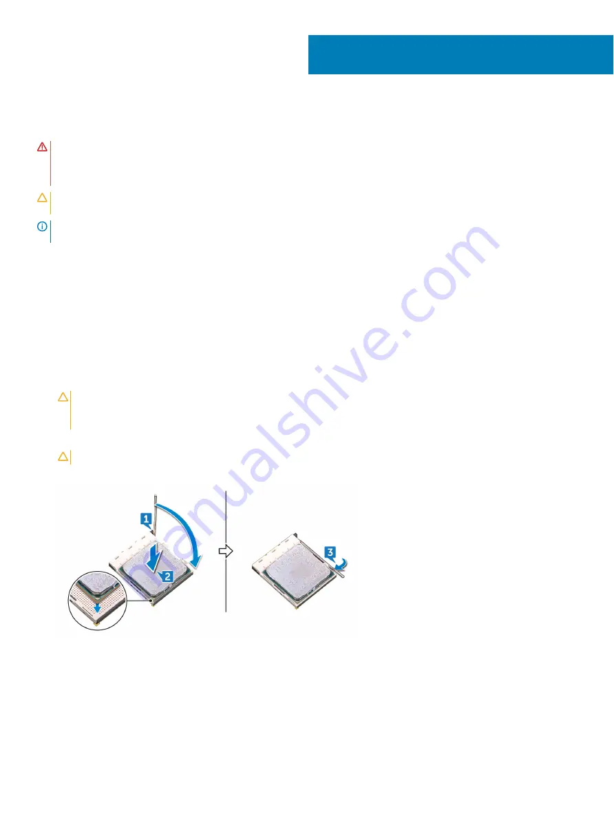
Ensure that the release lever on the processor socket is fully extended in the open position.
CAUTION:
The pin-1 corner of the processor has a triangle that aligns with the triangle on the pin-1 corner on the processor
socket. When the processor is properly seated, all four corners are aligned at the same height. If one or more corners of the
processor are higher than the others, the processor is not seated properly.
2
Align the notches on the processor with the tabs on the processor socket and place the processor in the processor socket.
CAUTION:
Ensure that the processor-cover notch is positioned underneath the alignment post.
3
When the processor is fully seated in the socket, pivot the release-lever down and place it under the tab on the processor cover.
4
Place the computer in an upright position.
Post-requisites
1
Replace the
.
2
Replace the
.
42
Replacing the processor
73
Summary of Contents for Inspiron 5676
Page 23: ...Removing the memory module 23 ...
Page 26: ...26 Removing the solid state drive ...
Page 30: ...30 Removing the 3 5 inch hard drive ...
Page 32: ...Post requisites Replace the right side cover 32 Replacing the 3 5 inch hard drive ...
Page 34: ...34 Removing the 2 5 inch hard drive ...
Page 36: ...Post requisites Replace the right side cover 36 Replacing the 2 5 inch hard drive ...
Page 46: ...46 Removing the wireless card ...
Page 54: ...Post requisites Replace the right side cover 54 Replacing the power supply unit ...
Page 58: ...58 Removing the left side cover ...
Page 64: ...64 Removing the processor cooling assembly ...
Page 72: ...72 Removing the processor ...
Page 80: ...80 Removing the front I O panel ...
Page 84: ...84 Removing the front panel light board ...
Page 94: ...94 Removing the power button board ...
Page 98: ...98 Removing the front bezel ...
Page 100: ...8 Replace the right side cover 100 Replacing the front bezel ...
Page 104: ...4 Replace the power supply unit 5 Replace the right side cover 104 Replacing the rear cover ...


